Such a dumb question. So dumb in fact that no-one bothers to mention it. How do you connect power to an op amp? Simple answer might be pos on the pos pin and neg on the gnd, but............. doesn't the signal input need to be referance to the mid voltage?
I.e with a 18V supply. doesn't the signal need to be referanced to 9V? I also assume that gnd needs to connect to the screen?
I see opamps with the max supply voltages at +/-18V ..... so the middle must be zero . Am I thinking too hard? Is that why I'm confused?
I.e with a 18V supply. doesn't the signal need to be referanced to 9V? I also assume that gnd needs to connect to the screen?
I see opamps with the max supply voltages at +/-18V ..... so the middle must be zero . Am I thinking too hard? Is that why I'm confused?
Hi,
most opamps are differential amplifers.
That means they amplify the difference between the inverting input and the non-inverting input.
If the opamp has been designed properly it does not care what voltage is fed to the +ve & -ve supply pins as long as the input signal(s) stay(s) between the supply voltages - ALWAYS!!!
I have seen some builders insisting on absolute accuracy for +-voltage matching and further stating that small errors in supply voltage matching will cause an equal output offset voltage. If the amp is any good this "error" is reduced by the PSRR of the amp.
Have a look at the datasheet and see what it says about PSRR and common mode rejection.
Most designs use a bipolar supply which provides a positive voltage and a mirror image negative voltage. These voltages are referenced to a third wire which is called "common."
The Opamp + input is referenced to "common."
The Opamp + input is referenced to "common."
Dumber please.
So I get from this that I aught to fix the signal to the +18 and -18V rails with (say) 10K resistors, making a voltage divider, and the middle is called "common".
What about gnd? what is that relative to?
One of my realworld projects for the future is to build a DI box running from phantom power (ignore the over-volt for a moment. Pos comes in on the output lines, and neg is on the screen, which is also gnd.
Though I don't really like anthropomorphic analogies, I find it helpful to pretend I'm a little guy inside the op-amp, having nothing at my disposal but a DVM and some resistances. I can measure from any pin, to any other, but I have no knowledge of anything outside the op-amp. My task in life is to measure the difference between the two input pins and connect resistances from the power supply pins, to the output, until the difference goes away. I do this quite quickly, so AC signals are no problem. Thinking in these terms, you can float the op-amp at any voltages you like, as long as you observe the CM restrictions. Ground is arbitrary- if you AC couple the input with a cap, you can use a divider to set the input DC voltage to half the supply voltage. You can also create an artificial ground, either with resistor divider, or with that, plus an op-amp buffer, but these approaches have a lot of problems in terms of impedance and stability. Better to AC couple if possible.
As a wild example of floating op-amps, there's a simple high voltage regulator circuit where a pass transistor controls several hundred or more volts. It's driven by an op-amp, with all pins at several hundred volts, the supply voltages being set by zener diodes off the HV line. The whole thing works great until somebody touches the thing with a scope probe, spiking the inputs, which have to charge up the capacitance of the probe, making the whole thing go up in smoke.
As a wild example of floating op-amps, there's a simple high voltage regulator circuit where a pass transistor controls several hundred or more volts. It's driven by an op-amp, with all pins at several hundred volts, the supply voltages being set by zener diodes off the HV line. The whole thing works great until somebody touches the thing with a scope probe, spiking the inputs, which have to charge up the capacitance of the probe, making the whole thing go up in smoke.
Hi,Pos comes in on the output lines, and neg is on the screen, which is also gnd
don't call signal and return Pos(+ve) or neg(-ve) that just adds to confusion.
Your signal on the pin and return on the screen are a pair of inputs.
The opamp is just waiting for you to connect these two inputs (signal and return) to it's two input pins. Any difference between those two inputs gets amplified and comes out of the output.
The schematic you use will show how to tie these three pins together.
It is quite common to call the screen, audio ground (but be specific to avoid another confusion). The circuit you build will probably use the screen as the reference for all other voltages going into and out of the opamp.
The opamp does not care where the supply pins voltages are provided you stick to that original rule
the input signal(s) stay(s) between the supply voltages - ALWAYS!!!
Andrew you misunderstood my post. Phantom power is: 48V DC pos on the 2 signal lines and 0V (return) on the screen ( I shouldn't have called it neg).
Its what to do with 0V DC and ground that confuses me if Common is actually (say) 18V higher than 0V
Its what to do with 0V DC and ground that confuses me if Common is actually (say) 18V higher than 0V
If you are useing a Standard Bipolar Supply like a +18v/-18v supply then the 0V is Ground .....(you could also use a Voltage divider between the +18v and -18v to create a Ground)
If you are useing a Single supply like a +36v supply you could Create a dual Supply by putting a Voltive divider between 0v and 36v and referance the input and all grounds to there.......
😀
If you are useing a Single supply like a +36v supply you could Create a dual Supply by putting a Voltive divider between 0v and 36v and referance the input and all grounds to there.......
😀
OK, now we are moveing into the more relevant replies, with Minion's last post...
Circuits can be powered by dual or single rail supplies.
Dual supplies, will have V+ = xV and V- = -xV and a 0V reference point for inputs and output signal... (gnd)
Single supplies Have a V+ = xV, a common reference of 1/2xV, and a 0V supply (the negative terminal on a battery for example)
Now comes the fun part....
when you use a single supply on its own, lets say with only a loudspeaker connected, the loudspeaker sees only the potential between the output and the reference point.... BUT this reference point is normaly some positive DC voltage... luckily DC is 'silent' allthough it will still melt speakers, so it needs a series capacitor on the output, to act as a gate only letting the AC signals (music) through...
As long as you don't have DC on the input to the power amp, it is irrelivant how a preceeding stage is powered... I.e. dual rail or single... once again, all that is important is the total potential voltage swing, and of course the input current the amp stage can handle...with a good dual rail, the signal could be very low DC offset removing the need for a DC blocking capacitor on the signal...
yes I'm down with the voltage divider part, and the decoupling cap, but if the input came down a bit of coax, What do you connect the screen to?
(There's more but that enough for a minute.)
(There's more but that enough for a minute.)
aaah I see
OK, so you have a blanced source?
try leaving it unconnected, or create a balanced signal buffer...
OK, so you have a blanced source?
try leaving it unconnected, or create a balanced signal buffer...
No no The simple bit first. Forget balanced for a moment.
Unbalance input down a piece of coax. Signal goes through a decoupling cap in into a "common" (between 0V and 36V) created by a voltage divider. Simple stuff, and its in every book.
But..........
What should I do with the screen?
Unbalance input down a piece of coax. Signal goes through a decoupling cap in into a "common" (between 0V and 36V) created by a voltage divider. Simple stuff, and its in every book.
But..........
What should I do with the screen?
Hi,
the screen is the other half of the input signal. It is connected via a few passive components to the other input pin of the opamp.
the screen is the other half of the input signal. It is connected via a few passive components to the other input pin of the opamp.
We are still not clear on the case here I think...
Possible scenarios...
Cable with single core, and a shield...
The core connects to input and shield would be to ground....
Cable with 2 cores and a shield
1) as above with each core representing a channel, and the shield shared ground...
2) balanced signal... 1 core +input, 1 core -input, shield grounded at one side only...
maybe a photo or schematic of what you are busy with will make the responses more usefull to you...
I'm sorry I brought the subject of balanced line up. It was a side issue, and I sincerly regret it. Forget the balanced line. As for photos, I haven't even started yet until i know what I'm doing.
It was a general question about how to power an op amp (any op amp) from a single power supply In this case a (theoretical) 36V DC.
1st rail is 36V ..... I know where this goes
2nd rail is 0V ...... I know where this goes. However, because we keep talking about:- low volt, shield, earth, 0V rail etc, I am now going to call this wire "John".
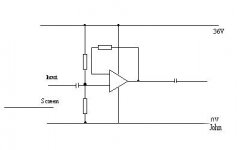
The input passes through a decoupling cap and is held at the comon voltage of 18V using 2 resistors which connect to 36V and "John".
That leaves the shield wire. Andrew says that It goes into the other input pin (Presumably it also needs a voltage divider). Nordic says that it goes to "Ground" I understand that there are alternatives with op amps. Does ground connect to "john"?
It was a general question about how to power an op amp (any op amp) from a single power supply In this case a (theoretical) 36V DC.
1st rail is 36V ..... I know where this goes
2nd rail is 0V ...... I know where this goes. However, because we keep talking about:- low volt, shield, earth, 0V rail etc, I am now going to call this wire "John".
The input passes through a decoupling cap and is held at the comon voltage of 18V using 2 resistors which connect to 36V and "John".
That leaves the shield wire. Andrew says that It goes into the other input pin (Presumably it also needs a voltage divider). Nordic says that it goes to "Ground" I understand that there are alternatives with op amps. Does ground connect to "john"?
Attachments
Hi,
does the input go to the non-inverting input pin of the opamp?
It looks like the output had returned to the inverting input via a resistor (Rupper).
Now connect a resistor (Rlower) between screen and the inverting input.
The gain of the stage is [Rupper/Rlower +1]. This is the standard non-inverting opamp stage with gain.
The two resistors between the supply rails and the input pin set the bias to keep the input between the rail voltages. Not a nice way to do it ,but it works with a few significant downsides.
On the other hand, if the existing resistor is returned to the non-inverting input pin and the input signal is connected to the inverting input pin then the opamp will settle with the output at or very near the positive supply rail. It will then ignore what happens with the input signal.
Pbassred said:It was a general question about how to power an op amp (any op amp) from a single power supply In this case a (theoretical) 36V DC.
1st rail is 36V ..... I know where this goes
2nd rail is 0V ...... I know where this goes. However, because we keep talking about:- low volt, shield, earth, 0V rail etc, I am now going to call this wire "John".
The input passes through a decoupling cap and is held at the comon voltage of 18V using 2 resistors which connect to 36V and "John".
That leaves the shield wire. Andrew says that It goes into the other input pin (Presumably it also needs a voltage divider). Nordic says that it goes to "Ground" I understand that there are alternatives with op amps. Does ground connect to "john"?
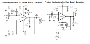
One tip is to look at the NS datasheet for the LM1875 chip, which is just an op-amp on steroids. You'll see two circuits, one for single-rail, one for dual-rail supplies.
With single-rail (page 2), a "virtual earth" is created at half supply voltage by the two equal resistors R1, R2 you note; it's added to the signal at the ingoing end and removed at the outgoing, allowing the signal to be magnified in-between, with the DC-blocking capacitors C1 & C6 preventing the high (half-supply) DC offset on the signal from leaving the amplifier at either end. Signal ground stays at earth (0V) potential throughout
Most op-amp basic circuits can be modified for single-rail use; there's a Texas Application Note SLOA058 giving examples.
- Status
- Not open for further replies.
- Home
- Amplifiers
- Chip Amps
- connect power to an op amp (dumb)?