Dear friends!
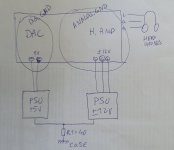
There is a DAC (digital ground, 3.3V supply) and a headphone amplifier (analog ground, +-12V supply). Both are located on the same board. How to connect both grounds correctly?
The figure mistakenly indicates 5V. In reality, it is 3.3V.
There is a DAC (digital ground, 3.3V supply) and a headphone amplifier (analog ground, +-12V supply). Both are located on the same board. How to connect both grounds correctly?
The figure mistakenly indicates 5V. In reality, it is 3.3V.
Attachments
If they're routed as separate planes under the respective circuits then join them at a single point using a ferrite bead / RF choke / jumper / thin PCB trace. The point is that they need to be common for the DC / audio frequencies but still block the HF rubbish due to the digital circuitry from entering the analogue section(s).How to connect both grounds correctly?
However, if they're already mixed up by the PCB designer then don't worry, just connect them directly. It is unlikely that the HF noise would even enter the headphones as voice coils are inductive on their own.
In either case, the headphone and digital supplies should have direct connections to the headphone and digital grounds respectively.
Last edited:

Thank you. They are separate planes so I'll choose the simplest method - connect them via thin trace near power supply pins on pcb
Henry Ott (RIP) has a paper on the subject:
"Grounding of Mixed Signal PCBs"
https://hott.shielddigitaldesign.com/techtips/split-gnd-plane.html
"Grounding of Mixed Signal PCBs"
https://hott.shielddigitaldesign.com/techtips/split-gnd-plane.html