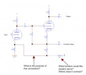
Attached is a schematic I made of the driver and concertina splitter from an old Lectrolab amp that was given to me after the last tech gave up. There is no available schematic of the amp, model S 950. I checked this a few times, the circuit is as I describe it.
The 47K resistor at the bottom right of the attached schematic was unconnected at one end, as shown. Can any one tell me:
- What function this resistor serves, where it might connect? The circuit would look like a standard self-biased concertina splitter without it (i.e., if there was a connection to ground in place of the 47K resistor).
- Why the driver cathode is connected to the cathode-end of the concertina?
Thank You!
Attachments
You should be able to trace the 47 KOhm resistor to the O/P trafo secondary. It's part of the NFB loop. The 47 KOhm and 680 Ω parts form the gain set voltage divider.
Thank you, Eli.
So current for the bottom half of the splitter flows through the driver-stage cathode resistor (680 ohm)?
So current for the bottom half of the splitter flows through the driver-stage cathode resistor (680 ohm)?
The current flowing in the NFB loop is tiny. Remember, the NFB loop is in parallel with the loudspeaker. For practical purposes, only a voltage is present. The values you provided feed back only 1.4% of the voltage applied to the loudspeaker. I suspect you have misread a resistance value. For instance, 4.7 KOhms combined with 680 Ω feed back 12.6% of the net O/P voltage, which strikes me as being a more realistic number.
I understand the NFB, and yes, we usually see a ratio of 1/20 or higher, so what you say makes perfect sense.
My last question doesn't relate to NFB, though. I'm sure this is garbled, but let me try again:
I'm wondering about the current source/path for the CATHODE of the tube on the right in the schematic, which is the cathodyne/concertina splitter. If there was no NFB, you would see it connect to ground (where the 100K and 47K meet in the schematic). This is a very common configuration.
Since there is no ground there in this case, where does cathode connect to ground? I see the path as going through the 1k8 resistor (generating the bias for the grid), then through the 100K, generating the current for the cathode, then over to the 680 ohm resistor which serves as the cathode resistor for the OTHER tube, the driver. Does it make sense for the cathodes of BOTH tubes to share that last resistor, and why?
I wonder if anybody else has tried the concertina strap to the cathode of the first stage and the results ? The 100K top and bottom resistors seem pretty high.
I'm assuming the concertina operates with no distortion but what benefit is there other than making the first stage operate more linearly ? I wouldn't have thought it was worth it.
richy
I'm assuming the concertina operates with no distortion but what benefit is there other than making the first stage operate more linearly ? I wouldn't have thought it was worth it.
richy
I suspect that's a mistake, since it would be detrimental to performance- the OP suggested that someone had been screwing around with the amp, fruitlessly. Perhaps that's where the trouble began?
I understand the NFB, and yes, we usually see a ratio of 1/20 or higher, so what you say makes perfect sense.
My last question doesn't relate to NFB, though. I'm sure this is garbled, but let me try again:
I'm wondering about the current source/path for the CATHODE of the tube on the right in the schematic, which is the cathodyne/concertina splitter. If there was no NFB, you would see it connect to ground (where the 100K and 47K meet in the schematic). This is a very common configuration.
Since there is no ground there in this case, where does cathode connect to ground? I see the path as going through the 1k8 resistor (generating the bias for the grid), then through the 100K, generating the current for the cathode, then over to the 680 ohm resistor which serves as the cathode resistor for the OTHER tube, the driver. Does it make sense for the cathodes of BOTH tubes to share that last resistor, and why?
Normally, unbypassed 680R at V1's cathode would be a negative feedback.
Reducing voltage gain and linearity of Mu, in return for an inreased linearity
of Gm. Assuming this is a voltage gainstage driving a very high impedance,
maybe a NFB here that only helps linearize Gm isn't a worthwhile tradeoff.
What you see is a positive feedback. Cancelling some or maybe all the NFB.
Result in fixed voltage at V1's cathode. Just like a bypass, but without the
extra capacitor. Allowing V1 triode's Mu to be in control, rather than Gm.
It is an attempt to be no cathode feedback, by virtue of PFB cancellation.
Thats why it looks screwy, you thinking all feedbacks must be negative...
----------
V2 wired as concertina, has entirely sacrificed Mu linearity for Gm linearity.
This type of linearity is fine too, but you could replace V2 with a transistor.
Function of Mu is made irrelevant by huge unbypassed cathode resistance.
Contrast V2's linear Gm against linear Mu function of V1!
Last edited:
In another forum, it was suggested that the circuit made more sense if the wire along the lower left connected to the bottom of the 680 ohm resistor instead of the top, ie. ground.
I was right to be curious on this: My 1960 dusty files came up with the circuit below: Well, it's lacking the o/p tranny global nfb stuff, but close enough to think about the combination.. My reckoning, in this circuit, oscillation and instability would have occured if the anode load of the first stage obtained it's volts from the conventional B+ way; But as the anode volts derived from the second stage cathode, the cathode voltage is in phase with the first stage triode anode (neg fbk) so stability results. The two cathodes joined is the positive feedback connection. I think I've got this right. So we have positive and negative feedback circuit. This circuit is a high gainer, except Miller effect makes effective gain slightly more than a sigle pentode stage. x100 x200.
Probably the ideal arrangement for an ECC83 but no further. Might try doing a 10W amp with this circuit and see how it turns out.The trick is to find the neutralised values of both pos and neg feedback to keep circuit stable. More math necessary.
Yes SY, someone probably botched alexages original.
richy
Attachments
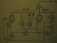
Interessant... V1a rigged as a Mu-Follower.
So R3 150K is a constant current source?
Might also explain why it does not ruin the
balance of the concertina.
And R2's NFB is bypassed by ~equal PFB.
We want Zero cathode feedback for best
Mu linearity, but don't have to nail exactly
for purpose of stabilty. PFB-NFB < 1 all that
stability requires.
R5/R2=Mu, no complicated maths necessary.
You can add a bypass cap, even a nasty
elko type for insurance. If PFB balance is
right, elko isn't conducting AC anyways...
I think R4 should have been bled to a fixed
(+Vb)/4 voltage, rather than its own cathode.
10Meg is a rather large value for grid bleeder.
Seems they are abusing electron capture on
V1b's grid to set an uncertain operating point?
Last edited:
Editing time limit expired...
R5 shoulda been 170K for best equal split?
On assumption R2 operates as-if bypassed.
R5 shoulda been 170K for best equal split?
On assumption R2 operates as-if bypassed.
Thank you all VERY MUCH for your thoughts and responses. This has been very interesting to me. Back to the Lectrolab circuit I started this thread with:
1. I am 99% sure the circuit as drawn is as manufactured. The amp has been butchered in the power supply area, but not elsewhere. The preamp section appears untouched, it was probably made in the late sixties. This isn't a big surprise, I can attest to the difficulty of simply accessing it, it is built on back to back eyelet boards, interconnected with short leads, and with plenty of connections made on the blind sides of the boards. I have quadruple-checked these boards, and do believe my schematic represents what is there.
2. This circuit is somewhat distant in physical layout from the speaker output/power supply, BUT the 47K resistor is located near the speaker output/power supply. There is a fairly long lead connecting it to the cathode of V1. So I was pretty sure the NC side of the 47K went to the speaker, ground (near the speaker ground), or to the bias voltage (yes, that would be "creative").
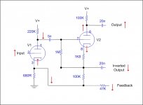
After reading all of the posts so far, I am most intrigued by the negative/positive feedback concept. The attached picture shows my limited understanding of what would happen to a positive input signal as it moves through the circuit. To my simple thinking, it results in positive feedback to the bottom of the concertina (V2), and negative feedback to V1, the driver stage.
Assuming the 47K is connected to one of the speaker outputs, could the positive feedback to the bottom of the concertina be an effort to create a better balance in the behavior of the splitter? I have read that the cathode output of the concertina, when over-driven, can cause grid current to flow in the output tube, more readily than the anode output, hence creating asymmetrical distortion. Is this circuit an effort to address that?
Eli, kenpeter, and richwalters, you guys are fantastic. Rich, I am especially impressed with that circuit you remembered from way back, that's a new one for me. Having access to this kind of collective knowledge base is a great thing.
1. I am 99% sure the circuit as drawn is as manufactured. The amp has been butchered in the power supply area, but not elsewhere. The preamp section appears untouched, it was probably made in the late sixties. This isn't a big surprise, I can attest to the difficulty of simply accessing it, it is built on back to back eyelet boards, interconnected with short leads, and with plenty of connections made on the blind sides of the boards. I have quadruple-checked these boards, and do believe my schematic represents what is there.
2. This circuit is somewhat distant in physical layout from the speaker output/power supply, BUT the 47K resistor is located near the speaker output/power supply. There is a fairly long lead connecting it to the cathode of V1. So I was pretty sure the NC side of the 47K went to the speaker, ground (near the speaker ground), or to the bias voltage (yes, that would be "creative").
After reading all of the posts so far, I am most intrigued by the negative/positive feedback concept. The attached picture shows my limited understanding of what would happen to a positive input signal as it moves through the circuit. To my simple thinking, it results in positive feedback to the bottom of the concertina (V2), and negative feedback to V1, the driver stage.
Assuming the 47K is connected to one of the speaker outputs, could the positive feedback to the bottom of the concertina be an effort to create a better balance in the behavior of the splitter? I have read that the cathode output of the concertina, when over-driven, can cause grid current to flow in the output tube, more readily than the anode output, hence creating asymmetrical distortion. Is this circuit an effort to address that?
Eli, kenpeter, and richwalters, you guys are fantastic. Rich, I am especially impressed with that circuit you remembered from way back, that's a new one for me. Having access to this kind of collective knowledge base is a great thing.
Attachments
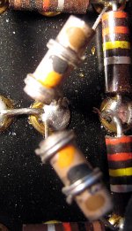
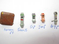
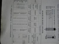
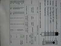
Those are capacitors. I can't remember how to read that color code, but it's in the appendix of any of the old Radio Amateurs' Handbooks. tubebooks.org - Vintage info from the age of vacuum tubes
Goo...... Going deeper in my cellar, I never thought these devils would resurface. I wished to see the end of them....I hate these types of caps, (the biggest non standard choas of the radio era) too easily read the wrong way round and which end to start. The throw-out can be both start and end figures. The Alexages pic would read 40pF; (anyone else agree on this ???) however can't be sure if there are more discrete markings on the body. The brown being tolerance 1% but by golly an RC meter is the best way. Expect considerable value drift over time. 40pF may appear an odd value, but not in the 1950's. Looking the otherway round would suggest 100000pF, (1 + zero and 4 noughts no chance)
Some examples shown in pic. The 51pF with the purple start on body, blows out the convention, poss being rare European.
Beware !
richy
Some examples shown in pic. The 51pF with the purple start on body, blows out the convention, poss being rare European.
Beware !
richy
Attachments
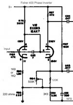
I'm not so sure the idea of positive and negative feedback inserted into the AF amplifier stage of a split load phase inverter circuit is so unique. Fisher did it in at least their 400 receiver, Dynaco did it in the ST-35, and the concept has often been used in phono preamp stages in at least in Dynaco and Eico designs as well. Basically, the positive feedback is used in increase OLG for more effective NFB when the loop is connected.
Dave
Dave
Thank you, Rich, they probably are 40pf, they show up all over the amp in areas where they would roll off high freqs, probably to avoid oscillation issues caused by lack of decoupling in the power supply, or who knows, maybe even problems arising from our splitter!
And thanks, DC. Reviewing the Fisher, along with the comments from others, causes me to think the circuit as I drew it will probably work.
We'll see. I'll get the power supply sorted out and working, and then find out what's working and what's not in the signal path. If that splitter gives me problems I'll just wire it up in a known-working config and take it from there.
I'll reply here when I do, just to "close the loop"!
All your "feedback" has been most "positive". Thanks!
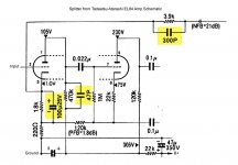
Examine this schematic: slight variation in first stage B+
http://www.tube-amps.net/images/EL84_PP_01/EL84_Schematic.jpg
richy
http://www.tube-amps.net/images/EL84_PP_01/EL84_Schematic.jpg
richy
Again, thank you all for being so helpful.
DC - you're right, the Fisher et al are very similar to this Lectrolab I'm working on. I work on guitar amps much, hi-fi little.
Richy - That Japanese EL84 schematic comes even closer, the only differences I see are value shifts that don't impact function, and some bypass caps to increase gain or stability. The website said this amp was modeled on a Rogers (London UK) monoblock from the mid-fifties.
BTW, I am beginning to think the 47K NFB resistor in the Lectrolab should be a 4K7, which would be similar to values in the above-mentioned examples. Perhaps someone mistakenly replaced it and the result was a bit of instability? Perhaps that's what drove the last tech to add about 3X more power supply filtering than I've ever seen in a guitar amp, and this one's a 15 watter at best. Shame, there was a lot of chassis butchery involved in all that.
One last question (famous last words)...
Both the Fisher and the Japanese circuits are sitting on top of ~200 ohm resistor - under the cathode of V1, bottom left. The Lectrolab does not have this resistor. See pictures attached.
What function does this resistor serve?
Attachments

- Status
- Not open for further replies.
- Home
- Amplifiers
- Tubes / Valves
- Concertina Splitter question - Need help