Ok, i am a second year EE student. that being said, dumb down any conversations on digital circuts or semiconductors or whatnot. also don't suggest things that are expensive!
problem: i have 2 cold cathodes in my computer case. they have a switch. i have to open the case to turn the switch off.
what i want: i want to control the switch via computer. my plan is to run some kinda signal to a transistor that will turn on a relay, or turn off a relay. the signal will come from the serial or parellel port.
what i had thought: some kinda Xor gate where the serial port is one input, and the ouptut is the other input. i don't have any idea why this would really work, and figure it is probably the hard way to do this all.
Why don't you just put a switch on the outside of the case?
Do you have a USB printer? or no printer at all?
Serial wouldn't be possible....
Parallel... EASY!!!
Just a sec.. 😀
Do you have a USB printer? or no printer at all?
Serial wouldn't be possible....
Parallel... EASY!!!
Just a sec.. 😀
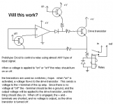
hmm, i had wanted something a little more dumbed down then that. I did think of something though. it involves 3 transistors involved as switches, and 1 op amp as a comparator, and a few resistors and a relay. possibly a coulple diodes. i'll attach the likely very wrong version. like i said, i'm new to semi-conductors.
Attachments
lol, I have a confession.. I don't even get the circuit I posted.. 😀 lol..... I have a circuit in magazine somewhere for a single parallel port controlled relay.... Don't know where it is though... as for the schematic you posted.. . umm.... I dunno.. 😀
see, my idea is that when the on signal is passed, it will make the transistor into a switch, and this will turn on the drive transistor. this will begin charging the relay. this will also send a signal to the op amp, which should be a non-inverting comparator. since the signal voltage is above 0, the opamp will send a signal to the drive transistor. once the "on" signal is let off, the drive transistor will still be on because it is controlled by the opamp, and the opamp will stay on because the drive transistor is on, so it will stay on. once the off signal is sent, the "off" transistor should act like a switch, and allow the same voltage to reach both terminals of the op amp, which will cuase the op amp to stop sending the signal to the drive transistor, which will cause the transistor to turn off, and the opamp should stay off.
i am wondering if it will work and if i drew it correctly, and if the relay's inductor will supply a signal to turn the op amp back on, which would mean that the thing would be hard to turn off.
i am wondering if it will work and if i drew it correctly, and if the relay's inductor will supply a signal to turn the op amp back on, which would mean that the thing would be hard to turn off.
Ummm... okay.. 🙂 lol... so, what exactly are you trying to do with this? have a program that you can use to toggle the relay on and off?? or what?? 😛 lol
controlling a relay via parallel port
Microsoft was never happy about controlling things on the outside from inside windows, thus you are going to have to noodle around a little in Visual Basic and perhaps get the DLL's which allow you to work around the operating system. The circuit below will control several relays or switches.
Be careful with the parallel port. You can fry your entire machine if you draw too much current on any pin.
Attachments
Well, as for software.. someone already wrote a rather nice Windows program....
http://www.aaroncake.net/files/index.html
To go with this circuit....

Also... 🙂
How To Program The Parallel Port In QBasic
How To Program The Parallel Port In Visual Basic
http://www.aaroncake.net/files/index.html
To go with this circuit....
Also... 🙂
How To Program The Parallel Port In QBasic
How To Program The Parallel Port In Visual Basic
hmm. I'll look into these. I am new at semiconductors, so i don't know how to get these things to work for me. I wanted something where you would supply a pulse, and the relay would turn on. another pulse on another terminal would turn the relay off.
could someone explain how circut with the octal something with inverted output works?
could someone explain how circut with the octal something with inverted output works?
I have had this idea for a while, and I think it may be of some use... use the "scroll lock" led.... what is scroll lock anyway?? who here uses it?? just run 2 extra thin wires from your keyboard to a circuit in your computer box (transistor and relay) that way you have either a button on your keyboard to tunr it on and off, or a porgram (I have one somewhere) that can be used to turn "scroll lock" on and off.... just an idea.. 🙂
Hi
Read this: http://www.techtv.com/callforhelp/answerstips/story/0,24330,3000289,00.html
Keld
what is scroll lock anyway?? who here uses it??
Read this: http://www.techtv.com/callforhelp/answerstips/story/0,24330,3000289,00.html
Keld
I don't use Microsoft Excel, or any Microsoft programs if I can avoid it.. 🙂 Ok, it has the same effect in the spreadsheet program I use, but COMMON!!! who needs it.. 😛 lol
since you are just trying to control a single device---cant you just read off the least significant parallel port bit.. write 00 to the parallel port when you want it off (all 0s), write FF to the parallel port when you want all 1's... Take the voltage off that pin, feed a NPN transistor as a switch to turn on your cathodes.. i dont think you need the relay as well, they dont draw much current, just get a transistor capable of how much power you plan on using.
perhaps something like this
that is not the correct connector for a parrallel port, i just through one in there.. you would habe to check which pin is least significant output bit, and it would be wise to get a connector, rather than shove a wire in there.. and it looks like the program on the previous post will work for addressing the parallel port. (http://www.aaroncake.net/files/icwin.zip)
good luck
-chris
perhaps something like this
An externally hosted image should be here but it was not working when we last tested it.
that is not the correct connector for a parrallel port, i just through one in there.. you would habe to check which pin is least significant output bit, and it would be wise to get a connector, rather than shove a wire in there.. and it looks like the program on the previous post will work for addressing the parallel port. (http://www.aaroncake.net/files/icwin.zip)
good luck
-chris
hmm, see that would require the parellel port always be outputing a signal. I hadn't wanted that really, since i don't know about the detailed workings of parellel ports.
I also saw a circut, and thoguht, maby i'm going about this all wrong, the easiest way may be to use the relay to power itself once the intial pulse enters. i know that's not the best description of what is going on.
time to find out how much current is flowing. should've done this from the start!
I also saw a circut, and thoguht, maby i'm going about this all wrong, the easiest way may be to use the relay to power itself once the intial pulse enters. i know that's not the best description of what is going on.
time to find out how much current is flowing. should've done this from the start!
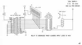
the circuit with the ULN2803
The UKN2803 is a very common chip -- each output is rated 50 Volts, 500 ma. The pullup resistors are necessary to provide clean outputs to the ULN2803a, R9 and R10 keep LPT1's ACK and ERROR ports high.<p>To get the device to work you can write a little code in basic to LPRINT a character to the LPT. All of the above is from one of the really basic books on computer interfacing "Controlling the World with your PC" <p>Once you get started playing with the PC's ports you have entered the abyss from which there is no escape. You will soon learn Visual Basic, C or Pascal!, then start programming PIC's and AVR's.
The UKN2803 is a very common chip -- each output is rated 50 Volts, 500 ma. The pullup resistors are necessary to provide clean outputs to the ULN2803a, R9 and R10 keep LPT1's ACK and ERROR ports high.<p>To get the device to work you can write a little code in basic to LPRINT a character to the LPT. All of the above is from one of the really basic books on computer interfacing "Controlling the World with your PC" <p>Once you get started playing with the PC's ports you have entered the abyss from which there is no escape. You will soon learn Visual Basic, C or Pascal!, then start programming PIC's and AVR's.
to my understanding, the parallel port does constantly output, not pulse. Anyway, if you wanted a pulse to activate something else, use a 555 timer in monostable mode. check this out for a decent tutorial on 555's
http://www.uoguelph.ca/~antoon/gadgets/555/555.html
http://www.uoguelph.ca/~antoon/gadgets/555/555.html
Here, read through this stuff. Should be lots of possibilities:
http://www.epanorama.net/links/project_interfacing.html
And here's a specific example:
http://www.xs4all.nl/~sebdehne/pp_powerSwitch/switch.html
You may need to substitute a Darlington transistor to get enough current to drive a lamp.
http://www.epanorama.net/links/project_interfacing.html
And here's a specific example:
http://www.xs4all.nl/~sebdehne/pp_powerSwitch/switch.html
You may need to substitute a Darlington transistor to get enough current to drive a lamp.
"or just flip and flop"
-i seriously can't wait to find out what that means.
I got a prototype working, but instead of the parellel port, i used switches. It is likely the mst complicated way to do what i want to do. also, i couldn't figure out how to get the non-inverting comparator to work. it stays on regardless of signal. if i could figure that out, i'd be able to get rid of my current attempt with an optocoupler.
how much current can the parellel port supply. i want to be very safe with this.
- Status
- Not open for further replies.
- Home
- General Interest
- Everything Else
- computer controled relay