I gathered these few simple two transistor compound preamplifiers. Would like to know if anyone built some like it, how it worked, which are best performing.
Are there web pages dedicated in designing these Sziklai simple circuit with explaining what part does what?
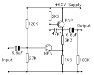
I noticed some sport feedback cap from output, some don't.
Just want to learn some more. Plus i just optimized nice 3 tap loudness volume pot, which reduces signal to some degree, so instead of simple buffer, i could built simple nice pre.
Are there web pages dedicated in designing these Sziklai simple circuit with explaining what part does what?
I noticed some sport feedback cap from output, some don't.
Just want to learn some more. Plus i just optimized nice 3 tap loudness volume pot, which reduces signal to some degree, so instead of simple buffer, i could built simple nice pre.
Attachments

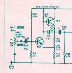


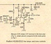
The one called 'Line Preamp' is from the Radford ZD control unit and is a text book implementation imo. It delivers really excellent performance, I have used these in the past.
Gain is (R33/R34)+1. R32 helps remove minority carriers from the base of the PNP transistor and greatly improves HF performance although the circuit will appear to work 'normally' without it. C26 tames the HF and phase response in a totally defined and controlled way.
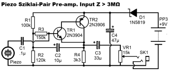
Your first image has a bootstrapped input stage (via C2) which allows the output voltage to modulate the bias voltage provided by R1 and R2. The effect of doing that means no voltage is developed across the 150k (and so the input impedance now appears as extremely high. Remove C2 and the input impedance is the 150k in series with the parallel value of R1 and R2. Voltage gain overall is '1' so a buffer.
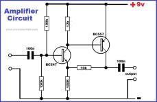
The others are all variations on the same themes but the Radford is the definitive one
Gain is (R33/R34)+1. R32 helps remove minority carriers from the base of the PNP transistor and greatly improves HF performance although the circuit will appear to work 'normally' without it. C26 tames the HF and phase response in a totally defined and controlled way.
Your first image has a bootstrapped input stage (via C2) which allows the output voltage to modulate the bias voltage provided by R1 and R2. The effect of doing that means no voltage is developed across the 150k (and so the input impedance now appears as extremely high. Remove C2 and the input impedance is the 150k in series with the parallel value of R1 and R2. Voltage gain overall is '1' so a buffer.
The others are all variations on the same themes but the Radford is the definitive one
As I recall, there was a complete Leach preamp project that used this topology. He probably explained the design as he did for the Leach Power Amp design published in "Audio" magazine in the 70s, too.
OK, found a link to the article, but did not reread it: https://leachlegacy.ece.gatech.edu/papers/wbpreamp/feb77article.pdf. I think he published a update later in 1977 for the power supply.
OK, found a link to the article, but did not reread it: https://leachlegacy.ece.gatech.edu/papers/wbpreamp/feb77article.pdf. I think he published a update later in 1977 for the power supply.