Another of my wild ideas.
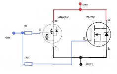
I have been wondering what would happen if a Lateral FET were paralled with a HEXFET ?
In a Class AB amp at low outputs the lateral would do all the work as the Vgs threshold of the HEXFET would not be reached.
As output increases then the HEXFET would come into play due to it's higher Vgs.
A quick examination of the Vgs characteristics between the two shows this "effect" may be possible. Also not shown, but perhaps using different low value source resistors could also be used to tweak the overall characteristic.
Attachments
A nice idea Mooly.
What would probably be an issue is the sudden break in gain or Gm when the hexfet comes in. That would cause a non-linearity in the OL transfer characteristic.
Possibly this can be tweaked or smoothed by giving the two devices each their own different Rs.
jd
What would probably be an issue is the sudden break in gain or Gm when the hexfet comes in. That would cause a non-linearity in the OL transfer characteristic.
Possibly this can be tweaked or smoothed by giving the two devices each their own different Rs.
jd
Vgs on a lateral is much, much less than for a hexfet, typically 0.5V versus 3.5V.
Consequently, to avoid current hogging, you'd really need to use a very large source resistor on the lateral. The crossover would then be handled by the laterals, with the hexfet chiming in at high power.
Another, perhaps better technique, might be to use a compound bias generator, so that both fets were biased on at quiescent, and 'in step' so to speak. But you are still up against very different transconductances, typically 1S for the lat and 5S for the hex.
This too is a complicating factor, but, I suspect it's doable.
Hugh
[snip]Another, perhaps better technique, might be to use a compound bias generator, so that both fets were biased on at quiescent, and 'in step' so to speak. But you are still up against very different transconductances, typically 1S for the lat and 5S for the hex.
[snip]Hugh
Yes good idea.
jd
Jan and Hugh, thanks for your thoughts. A compound bias generator sounds intriguing although I guess my thoughts were to have the hexfet have zero contribution (and hence run cold) until it was "called into action". Almost like a form of current dumping as it were.
Would that OL non linearity be audible I wonder as it would occur at high level and be under control of NFB, hmmm, plenty to think on I guess.
Would that OL non linearity be audible I wonder as it would occur at high level and be under control of NFB, hmmm, plenty to think on I guess.
Current dumping doesn't have the problem of a bend in the OL transfer as it works by modifying the feedback factor when the dumpers come on.
That's an option: use the laterals as low power class A and use the hexfets as current dumpers in a current dumping bridge. But it's a bit more involved 😉
jd
That's an option: use the laterals as low power class A and use the hexfets as current dumpers in a current dumping bridge. But it's a bit more involved 😉
jd
Indeed, Mooly, worth a try as a compound, and in truth you can still 'dump' on the hexfet with judicious biasing and choice of Rs.
This would involve some modelling (not too much, laterals have poor PSpice models) and a lot of building and testing. If you use global feedback, there is no reason why the abrupt change in transconductance, albeit at some higher voltage than crossover, could not easily be accommodated into a smooth transfer.
Cheers,
Hugh
Yes it might even look like Doug Self's XD but symmetrical around the zero output point.
I think the main idea would be to:
- make the laterals work in class A for some small power range like the First Watt 😉 ;
- smoothly bring in the hexfets. The 'smoothly' is very important: the smoother it happens, the lower order the harmonics from the non-linearity will be and the better the feedback can ehh... smooth them out.
jd
I can't model a parallel pair in my head, so I am way out of my depth, but here goes.
Run the Laterals with a conventional Rs to give your 1W of ClassA (Ib=250mA)
Add a large Rs to the Vfet to bring it's transconductance down from that high 4s to 5S starting value. Ib~0mA
As signal voltage rises the Vfet starts to turn on and gradually comes in to match the current flow of the Lateral.
Is it any more complicated than that? Probably!!
Yes it might even look like Doug Self's XD but symmetrical around the zero output point.
jd
That's an intriguing thought 😉
"First watt" class A... nice one ! I might give the idea some serious thought.
Is it any more complicated than that? Probably!!
Dunno tbh... it's probably as complex as you want to make it, like most things really.
The devil would be in the detail for sure.
This would involve some modelling (not too much, laterals have poor PSpice models) and a lot of building and testing.
Cheers,
Hugh
😉 It's just below this Hugh, my signature 🙂
Building and testing is nearer my mark... with a lot of good old empirical design thrown in for good measure.
I know we think alike sometimes on the way our amps sound, and that just "perhaps" a certain distortion spectrum can really do wonders for creating something truly magical.
Member
Joined 2009
Paid Member
I like many of Wavebourn's ideas. I think he is very clever...... and there are lots of others here too, though they hide their light under a bushell (Mooly?? You there??)
Hugh
Hugh
this reminds me of the bjt fet combination that Wavebourn likes - not sure where it was used though....
Wavebourn probably has used it in several cases.
But the topic is this:
http://www.diyaudio.com/forums/headphones/90324-best-sounding-headphone-amp-wavebourn-kubeek.html
You have Wavebourn's schematic in first post.
We had some discussion and I even did some SPICE with different BJT + MOSFET output devices.
Such combinations are not mainly used to lower distortion, but to change the type of dist.
Member
Joined 2009
Paid Member
Wavebourn probably has used it in several cases.
But the topic is this:
http://www.diyaudio.com/forums/headphones/90324-best-sounding-headphone-amp-wavebourn-kubeek.html
You have Wavebourn's schematic in first post.
We had some discussion and I even did some SPICE with different BJT + MOSFET output devices.
Such combinations are not mainly used to lower distortion, but to change the type of dist.
The image I posted above has the BJT and MOSFET essentially in parallel, as Mooly had suggested. Isn't the headphone amp different, it is more like a P-P combination of BJT and MOSFET i.e. the Wavebourn Tower.
By the way - I also have a great respect for Wavebourn's ideas, they are original. Soon I will have my first tube amp finished and then I am ready for a hybrid and perhaps it will be a Tower 😀
Last edited:
- Status
- Not open for further replies.
- Home
- Amplifiers
- Solid State
- Compound Lateral FET for higher power Class AB amp.