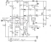
I received a request from rsumperl for a custom designed PCB for a Dynaco MK3 PCB using a 6u10 Compactron tube. I did several amps with the little tripple triode and offered my services. After sending the schematic and concept PCB layout, I have not heard from him, so I'm putting the design up for anyone to use. It is a concept based on amps that I've built. I do not know the exact dimensions of the Dynaco Chassis so I just did a guess.
It uses the high gain triode for the input stage and the 2 medium gain for the LTP. It utilizes a CCS in the tail and the outputs are buffered by MosFet class A followers to prevent blocking distortion. This is all I believed that would fit through the hole in the chassis and would be the best circuit topology based on my past amps.
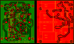
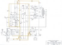
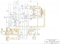
The PCB set are designed so the B+ bias and voltage supplies mount to a piggy back PCB on the back side. I've used the metal pin connectors from various plastic housing connectors for this concept. This simplifies the chassis wiring. The jpgs show the power PCB wiring and the chassis wiring. I also include the first concept schematic of the main PCB.
The metal connectors connect at the strategic locations suppling the needed bypassed voltages for the driver PCB.
There are several tripple triode Compactrons for rolling.
It uses the high gain triode for the input stage and the 2 medium gain for the LTP. It utilizes a CCS in the tail and the outputs are buffered by MosFet class A followers to prevent blocking distortion. This is all I believed that would fit through the hole in the chassis and would be the best circuit topology based on my past amps.
The PCB set are designed so the B+ bias and voltage supplies mount to a piggy back PCB on the back side. I've used the metal pin connectors from various plastic housing connectors for this concept. This simplifies the chassis wiring. The jpgs show the power PCB wiring and the chassis wiring. I also include the first concept schematic of the main PCB.
The metal connectors connect at the strategic locations suppling the needed bypassed voltages for the driver PCB.
There are several tripple triode Compactrons for rolling.
Attachments
Last edited: