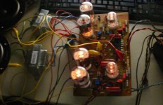
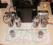
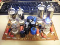
Just finished stuffing the board and applied power without speaker global feedback. The Monster lives, but with the global output feed back, less gain and is much better behaved, more refined sound quality.
6U10 for input and LTP driving 6JN6 (or 6JM6 with plate cap) output tubes running in triode mode. Pots for balancing and adjusting output current worked, running 40ma Iq with less than .001 volt mismatch across the 10ohm resisters.
This is my first tube amp project, PCB was a challenge with the ironed toner resist method, used same method for front component identification..
eyelets for all through holes for wiring and back mounted caps.
Next, try different output transformers, refinement and put into a box.
Next project selected is a KT88 design driven by 6N6H Russian tubes LTP and 6SN7 front end to allow for tube / tone character selection.
SO many tubes, SO little time....
Attachments

Congratulations !
Good morning Roline,
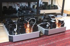
congratulations with the Compactron-amp.
For my last amplifier i used Compactrons as well. First a 6HV5 for the combined task as input/driver for the 35TG. It worked....but did not sound nice. Then i switched to the dual-different-triode-family (6FY7, 6FJ7, 6FM7) with great results. The first triode inside the Compactron as input; the second as driver.
As you said: so many tubes; so little time. And the variety of Compactrons is amazing; the price as well.....
Lots of luck with the building. Enjoy your creation.
Regards, Reinout
Good morning Roline,
congratulations with the Compactron-amp.
For my last amplifier i used Compactrons as well. First a 6HV5 for the combined task as input/driver for the 35TG. It worked....but did not sound nice. Then i switched to the dual-different-triode-family (6FY7, 6FJ7, 6FM7) with great results. The first triode inside the Compactron as input; the second as driver.
As you said: so many tubes; so little time. And the variety of Compactrons is amazing; the price as well.....
Lots of luck with the building. Enjoy your creation.
Regards, Reinout
Attachments
Looks cool, but substations that have such voltages have shields and scary pictures... It is more dangerous than electric chair, because it looks cool, and don't resemble a killing machine! I mean Reinout's picture.
I have a design that uses 7193 and 615 mickey mouse tubes, all with top cap connections.... to drive the outputs. There are several output tubes also with the plate cap....
Something to keep the finders out of. I was under the impression that it was done for capacatance reduction for a higher power band width..
Something to keep the finders out of. I was under the impression that it was done for capacatance reduction for a higher power band width..
Nice as those all metal plate caps look, I'm far more comfortable with ceramic ones or an enclosure.
That PCB look just awesome, obviously a lot of care and trouble went into its design and fabrication..
That PCB look just awesome, obviously a lot of care and trouble went into its design and fabrication..
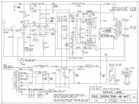
Thank you for posting the schematic! Do you have any PCB layouts you can share? I know it's still "beta"
Thanks,
Ray
Thanks,
Ray
Compactron PCB
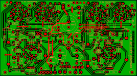
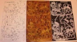
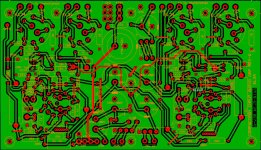
The software I use is from Express PCB which is not gerber file compatable. They want you to order the PCB's from them which is a viable option. I print it out, correct the ground plane with white-out and then use a copy on hi-clay slick paper toner transformation method to iron fab the boards. I've only attempted single sided due to not having electroless plating capability for doing the through holes. The major change from revB to F was adding leds to illuminate the tubes from under the PCB and increased the bypass capacitor on board needed to shake the woofer cones while playing the heartbeats from "Dark side of the moon". I put a trace to the back of the board for B+ output transformer connection. For the prototype I just added a couple caps off board.
I played around today doing a ground plane top layer (red). Several articles I've read have stated, excessive capacatance will reduce the frequency response.
I guess the purists would only consider point to point wiring.
Attachments

Compactron continued
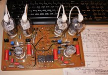
Got started on packaging, sheet metal measures 12x11.5". Also started to design the chasis wood. Need to find knobs. I hooked it up to a set of 4ohm Orions and adjusted the bias up to 60ma through the output tubes. I have a set of RCA's 6JN6's to put in it when I'm done with the construction, just using a mixed set for now. I've been using Sylvania and GE's for inputs.
CSN&Y had better imaging than with the Onkyo SS amp, Wear and Wasserman played with authority.
I wonder what it would sound like with a couple hundred extra volts on B+ and a output set of 6KD6 outputs? A thread on DIYaudio revealed that Pete Millett's Engineer's Amp cranked out 500 watts, with enough B+ with the amp parallel as a mono amp. There is a great article on DIYaudio search under
Posted new P-P power amp design
Tubelab.com puts it through tube inferno with different voltages, transformers, and output tubes. He fried a couple resisters, and puked a few caps in the process. I was trying to keep the supply civil under 450V for 450V caps, I did not want to stack them, but that is an option if I do it off board.
One mod to the supply was removing the CL80 from the -70V bias circuit, the inrush limiter could be a liability to the bias stability.
Attachments

Last edited:
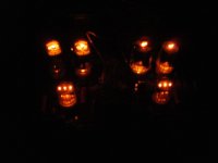
Elves work overtime on Compactron stocking stuffer
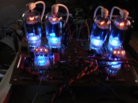
All but the knobs and upgraded iron. I have 1650H iron on back order and the elves missed delivery of the aluminum knobs, so I had to scrounge through the misc box to find something short term.
The nixie tube displays what tube's bias current is on the amp meter. It can be switched to "0" or blank when not connected to any of the bias resistors for normal operation.
Great clarity and large image with the little iron, can't wait to see what it can do with real iron...
Simple amp, MP3 input in the front and RCA's in the back, currently about 22-25 watts/channel, with the 8k-8 transformers, anticipate 40/channel with the 1650H's 6.6k hooked up as 3.3k.
Elves are looking for a larger sock for this stocking stuffer, as well as started another one for themselves.
Stacked caps on the power supply for higher voltage B+, as well as a full set of 6LB6 tubes are on their way, quite a difference in plate area between the 6GM6 and 6LB6 tubes.... Also put in provisions for the tacky blue led tube illumination, the clear glass bottoms allow for instead of using an illuminated front switch, just another option, Caps go on the back side for mounting clearance...
I also did a PCB layout for EL34's/ 6l6's to try it in UL mode. Might try to etch that one over the holidays.
Question to all, any good/simple 600v to 450v volt shunt or pass regulators at 200ma?? If I use a voltage doubler, I'l have to drop it to the cap voltage of 450 volts, or use an off board stack. Please advise
Attachments
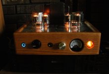
Compactron, one for the elves.
Caps but one mounted on back side, 6GM6's selected. Just waiting for a few parts to show up. May have to substitute to fire it up.
Does anyone have a good and simple B+ regulator, I'd like to use a voltage doubler and regulate it for a set of 6LB6 output tubes.
Caps but one mounted on back side, 6GM6's selected. Just waiting for a few parts to show up. May have to substitute to fire it up.
Does anyone have a good and simple B+ regulator, I'd like to use a voltage doubler and regulate it for a set of 6LB6 output tubes.
Attachments
Question to all, any good/simple 600v to 450v volt shunt or pass regulators at 200ma?? If I use a voltage doubler, I'l have to drop it to the cap voltage of 450 volts, or use an off board stack. Please advise
Could you use a choke input filter? Seems like the easiest way to drop a lot of extra B+.
Cool amp!
I've seen those 12 pin tubes but never anybody that used them.
I really like the wooden bases you guys come up with.
I've seen those 12 pin tubes but never anybody that used them.
I really like the wooden bases you guys come up with.
I've seen those 12 pin tubes but never anybody that used them.
The 12 pin Compactron tubes were designed for TV sets. Some of the bigger sweep tubes were used in big audio amps lick the Macintosh MI-350. Some versions were used to near extinction in ham and CB linear amplifiers. Those tubes are expensive today. Many 9 and 12 pin tubes were nade but the term Compactron was GE's trademarked name that is now a general term. Three sections of the popular 12A_7 tubes were stuffed into a single glass envelope. The 6U10 is 3/2 of a 12AX7 iirc. They were used in some guitar amps. Ampeg was one user.
For a long dissertation with a working design on the merits of some of the common 12 pin sweep tubes suitable for audio amps up into the mega power range see this thread:
http://www.diyaudio.com/forums/tubes-valves/151206-posted-new-p-p-power-amp-design.html
I started playing with the compactron tubes when I found several 6U10's on Fleebay for shipping cost. I liked the idea of 3 tubes in one and though it would be a good input for a simple chicken s?it little compact amp. Input stage and phase splitter all in one. Is it the very best selection for each application?, I doubt it. But I was wrong in my assumptions. First, the little 6U10 has proven to be adequate and low noise for driving the outputs. I replaced the 6JM6's with 6LB6's, reduced the GNFB and survived blowing a silver mica cap, little bugger put up smoke signals! 500 volt rating at only at 300Volts. The 10lb transformer 55 volt tap was a little weak, so I used one of the spare 6.3 volt taps to boost it a little, much better control over the output tube bias. Back to the assumption. The clarity and sound stage is much better than I had hoped for. I will still work on the kt88 amp, but this one still has opportunities for simple upgrades, like increased B+ perhaps to 400, 450 volts. 60 watt Hammonds are only about 1/4 inch longer than the 40's, etc...
More fun than watching TV!
More fun than watching TV!
Attachments

- Status
- Not open for further replies.
- Home
- Amplifiers
- Tubes / Valves
- Compactron amp... LIVES!