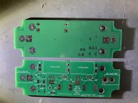
Here's a compact SMPS filter using the AmyAlice circuit. It includes an optional switch circuit to kill the power and prevent "preamp turn on thump" when used with the ACA mini. Unfortunately, I don't have the test equipment to see if my layout performs equal to the MJ PCB but it sounds good to me! Feel free to use the attached gerbers and BOM as you see fit.
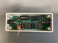
Assembly notes: I used the manufacturer's footprint for the inductors and I find the pads are almost entirely hidden under the device. As a work around, I was able to solder one side and then slide it over a wee bit under heat to do the other side. Also, the double sided foam tape under the PCB did not have the protective strips removed as I only used it to provide some backing tension for the #2 PCB mounting screws. If you don't use the screws, you can use it as mounting tape. Getting the enclosure holes located exactly right is the hardest part. The input/output DC jacks can be slid fairly close to the insides of the box. I recommend tacking them to the PCB using only the + terminal and double checking the fit and adjusting as necessary before final soldering.
R1 update notes:
Change D1 P/N to 576-P6SMB68A
enlarge L1 and L2 footprint solder pads to facilitate easier soldering
Attachments

Last edited:

Congratulations @avdesignguru !! Your board looks fantastic and I bet lots of builders will be interested.
I have linked to this thread from AmyAlice post#1
I have linked to this thread from AmyAlice post#1
Last edited:
First off, thank you to @avdesignguru for their generosity in sharing this project with Diyers (and of course @Mark Johnson too for the original design).
I wanted to ask for some advice from the community after my attempts at soldering this board - for an ACA Mini and ACP+.
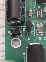
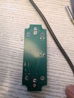
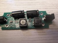
I tried building 2 of the boards this weekend, both unsuccessfully (my first attempts at SMD). I was able to power on an ACA Mini ("Board 1), but audio was very distorted and low in volume. Other board ("Board 2") did not function.
I checked component values before installation. Then the continuity path leading to from components/resistances in place for each part after I installed them. I also double-checked polarity of parts (cathode band of D1 at the 'top' of the board)
As this was my first SMD project, I imagine I might have overheated and fried D1?
Finally, for the male power plug I used this from Amazon - which cagily recommends 12V maximum, but says up to 24V. Unsure if this could also be part of the problem.
Thanks for any help!
I wanted to ask for some advice from the community after my attempts at soldering this board - for an ACA Mini and ACP+.
I tried building 2 of the boards this weekend, both unsuccessfully (my first attempts at SMD). I was able to power on an ACA Mini ("Board 1), but audio was very distorted and low in volume. Other board ("Board 2") did not function.
I checked component values before installation. Then the continuity path leading to from components/resistances in place for each part after I installed them. I also double-checked polarity of parts (cathode band of D1 at the 'top' of the board)
As this was my first SMD project, I imagine I might have overheated and fried D1?
Finally, for the male power plug I used this from Amazon - which cagily recommends 12V maximum, but says up to 24V. Unsure if this could also be part of the problem.
Thanks for any help!
Attachments

@jt23:
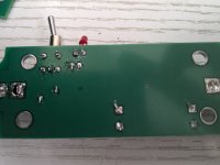
This is a pretty simple circuit. I don't see anything obvious with your component polarities but your soldering is a bit rough.
I'm assuming your 24VDC supply is center pin positive. I'm also assuming you have 24VDC at the output jack. If not, with nothing plugged into the filter board, you should show pretty much an open circuit (over 1 meg ohm) between input jack center pin and outer barrel input supply ground (power switch on). It may take a few moments to get a final reading based on the input impedance of your meter.
You should also have a very low resistance from the input center pin to the output center pin, maybe 0.3 or 0.4 ohms. And 0.1 ohm or less between input jack barrel and output jack barrel connections. And be sure that your D1 protection diodes are 68 volt and not 6.8 volt.
The Amazon power cords are the same as I bought and are high quality 18 gauge. No problem with using them at 24VDC.
Yep, ACA Mini Meanwell store supply - checking the datasheet I believe it is center pin positive.I'm assuming your 24VDC supply is center pin positive. I'm also assuming you have 24VDC at the output jack.
Yes, meter shows open circuit ("OL").with nothing plugged into the filter board, you should show pretty much an open circuit (over 1 meg ohm) between input jack center pin and outer barrel input supply ground
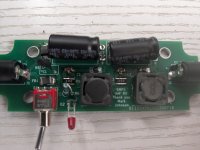
I should have checked this more carefully. There is a 750 ohm reading from input center pin to output center pin. Looks like the 2nd RL stage inductor isn't soldered correctly...You should also have a very low resistance from the input center pin to the output center pin, maybe 0.3 or 0.4 ohms.
If the inductor doesn't fix the issue, I will likely try again with a fresh board and new parts. Perhaps with more practice kits under my belt.
D1 diodes are the 68V version. Good to know about the power cords.
Really appreciate your help with this, and I'm looking forward to having working filters in the future after I brush up on my manual skills. I'll definitely do some DCR sense checks, checking against the schematic, too.
jt23:
You might try using some paste flux on the pcb in addition to a good SN63 flux core solder. Something like this:
https://www.amazon.com/SRA-Electronics-Soldering-Electronic-Electrical/dp/B0B2HXJNMB
You only need a little bit on the pad, using a toothpick or something like that. Really helps a lot.
Also, I updated the BOM for the 68v TVS diode. Turns out I needed to specify the simplified part number, P6SMB68A. Mouser number for that is 576-P6SMB68A.
Think I was a little heavy handed with the paste. Will exercise caution next time.You only need a little bit on the pad, using a toothpick or something like that. Really helps a lot.
But I have music now from the ACA mini! Thanks again for the help. I'm looking forward to getting to know how it subjectively affects SQ.
- Home
- Amplifiers
- Power Supplies
- Compact SMPS filter using AmyAlice circuit design