Can some one help explain 6C33C OTL circuit
Hi I am in the process of building a SET with 6C33C-B tubes, I found this tubes are also used in OTL amps, and the idea of building an AMP without having to invest in Output transformers seems excellent.
I have been reading about OTLs and came across this design form Eugene Kremiński from Lviv, Ukraine which is highly regarded by Lampizator. Is this design worth a try?
I really don't understand how the thing works, can anybody here comment and on the circuit design, pros and cons, has anybody built something similar?

Any explanation is welcomed.
Hi I am in the process of building a SET with 6C33C-B tubes, I found this tubes are also used in OTL amps, and the idea of building an AMP without having to invest in Output transformers seems excellent.
I have been reading about OTLs and came across this design form Eugene Kremiński from Lviv, Ukraine which is highly regarded by Lampizator. Is this design worth a try?
I really don't understand how the thing works, can anybody here comment and on the circuit design, pros and cons, has anybody built something similar?
Any explanation is welcomed.
Last edited:
Hi I am in the process of building a SET with 6C33C-B tubes, I found this tubes are also used in OTL amps, and the idea of building an AMP without having to invest in Output transformers seems excellent.
I have been reading about OTLs and came across this design form Eugene Kremiński from Lviv, Ukraine which is highly regarded by Lampizator. Is this design worth a try?
I really don't understand how the thing works, can anybody here comment and on the circuit design, pros and cons, has anybody built something similar?
Any explanation is welcomed.
It's a circlotron. A nice, very symmetrical, output stage. You can find various discussions and explanations on the internet if you google for circlotron. One nice discussion is in John Broskie's article
http://www.tubecad.com/articles_2003/Cars_Planes_Circlotrons/Cars_planes_circlotrons.pdf
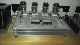
where he explains a bit about it, and contrasts it with the other common OTL output topology, the totem pole. John Broskie has various other articles discussing OTL amplifiers on his website. I've built a couple of OTLs using 6C33C tubes; both of them are totem pole rather than circlotron, but they give a really nice sound. I've also built a circlotron using EL509 sweep tubes. Personally, having got into OTL, I'd never go back to building amplifiers with output transformers.
Chris
Thanks Cnpope, Broskie's article is very enlightening even though I don't get one half of the stuff. I know transcendent sound, I even have Rozenblitz's two books, so I know about his patent. Very polemic issue this of Rozenblitz's patent being just the same OTL circuit of old. Needless to say I only get the airplane car analogy, but I don't get a bit of the explanation "dumb me".
Can the power supply units in this Cicltron design be replaced by solid state regulated ones? What is the use of the hybrid power supply? is it just to delay start? What is the function of inductance LD1, LD2 and LD3? Are the really necessary?
Can the power supply units in this Cicltron design be replaced by solid state regulated ones?
Yes. It would be an improvement.
What is the use of the hybrid power supply? is it just to delay start? What is the function of inductance LD1, LD2 and LD3? Are the really necessary?
These are ripple filter chokes. It requires a separate PS for the front end. The finals can pull the required bigamps at very low voltages, but the front end requires higher voltage so's it can operate with good linearity. Passive filtering is easy and reliable. However, chokes that can handle the current demand of the finals are going to be quite heavy, as they'll need a lot of iron.
These could be replaced with either active decouplers, or active regulators. The whole back end could be replaced with power MOSFETs that can handle the current demand, and do it without requiring the heater power. Any VT that can handle bigamps will have power hungry heaters.
I have built something similar, so if you do your job right, you are in for a pleasant surprise, it should sound good!
L1 is needed, but I don't think you need L2 and L3 - it a balanced system (if you bias it right) so you could save money and space by omitting them, also you probably don't need so many 680uF smoothing caps, two per side is enough, I would bypass them with roughly 4.7uF polyP capacitor.
Coupling capacitors (0.47uF) play a big role in the sound quality, I tried so many, my final choice was cheap Russian K40y-9's.
Also use a good quality (Nichicon fine gold) for the 100uF/250V in the first section.
P3 and P4 are bias trimmers, P2 is balance trimmer, balancing the phase splitter (first section).
If your preamp or DAC has balanced output (XLR) you could use grid on L1B and L1A for your balanced input.
Explanation of circuit:
L1A and B is the first tube, being a twin-triode. It is used in a long tailed format, as input stage/phase splitter. P2 balances the first stage, R9 supplies the negative supply.
The output from this stage goes to L2A and B which is the driver section again in long tail.
Circuit is clever enough to use DC coupling to the driver section.
The driver section is coupled to the output Migs by capacitors, P3 and P4 bias the output tubes. you should measure the voltage drop across the 1 ohm resistors on the plates (R18 and R19) in order to set the bias. I would measure voltage drop across one of them first and set the bias to whatever the design says so. I would not connect speakers yet,connect an 8 Ohm (or so) across the speaker outputs as load. I would then adjust the other trimmer, to get as near to zero DC voltage across this load, check your adjustment after 30 mins to make sure nothing has drifted.
There are four power supply sections.
2 identical 150 V for the output tubes, a tube based HV for the input section and driver, and a last negative one to supply about -70 V for biasing the output tubes.
I used solid state for all, no tube rectification, but I did use 22nF snubbing capacitors on all my diodes.
What is puzzling, is that I do not see any feedback section on this design! Hmmm
I would have split R7 into four resistors, about 16k in series with a 500R for each triode section, and then get two feedbacks from speaker terminals to the 500R's as feedback.
Hmmmm
The weakness in this design is the adjustment required in the first stage of gain, which is direct-coupled to the second stage.
We used to build this circuit back in the 1980s. We never did get it to work right; the 'AC balance' pot is just asking for trouble. If the circuit is out of balance it distorts, to correct it you make the first stage distort... can't win for loosing.
We had better success with a differential cascode circuit, which has better performance and no need for the balance control.
You can read about this OTL on the thread entitled "What tubes for a tube amp?"
http://www.diyaudio.com/forums/tubes-valves/161112-what-tubes-tube-amp.html
- Status
- Not open for further replies.
- Home
- Amplifiers
- Tubes / Valves
- Comments on 6C33C-B ARG OTL