Hello!
I have managed to get ahold of a Sunfire Cinema Grand 200x5 with one broken channel that I would like to try and fix.
The power supply is working and all channels except rear right is working properly. I know this is a complex design and no schematics that matches the actual PCB is available.
After visual inspection I noticed at burnt area and that someone had tried to repair it. I cleaned it up and replaced the resistors with proper values.
After that i have a wave form! Much closer to fixing this already!

I would really appreciate some comments on the distortion. Is this crossover distortion? Should I look toward faulty transistor or could this be caused by bad caps?
I would like to probe this with the scope to look for the problem but without a schematic I'm a bit out of my comfort zone 🙂
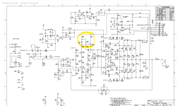
Attaching the schematic. It's accurate enough to get an idea, but the components IDs are not the same as on the actual pcb.
The area were the bad repair had happend, that I cleaned up is marked in yellow. Before this the wave form had no positive cycle. 🙂
Any input that could nudge me in the right direction would be greately appriciated!
Best regards,
Daniel Elvin
I have managed to get ahold of a Sunfire Cinema Grand 200x5 with one broken channel that I would like to try and fix.
The power supply is working and all channels except rear right is working properly. I know this is a complex design and no schematics that matches the actual PCB is available.
After visual inspection I noticed at burnt area and that someone had tried to repair it. I cleaned it up and replaced the resistors with proper values.
After that i have a wave form! Much closer to fixing this already!
I would really appreciate some comments on the distortion. Is this crossover distortion? Should I look toward faulty transistor or could this be caused by bad caps?
I would like to probe this with the scope to look for the problem but without a schematic I'm a bit out of my comfort zone 🙂
Attaching the schematic. It's accurate enough to get an idea, but the components IDs are not the same as on the actual pcb.
The area were the bad repair had happend, that I cleaned up is marked in yellow. Before this the wave form had no positive cycle. 🙂
Any input that could nudge me in the right direction would be greately appriciated!
Best regards,
Daniel Elvin
Attachments
Crossover distortion caused by too little idle current.
Check for damaged Bias components.
Check for damaged Bias components.

it does look like crossover distortion to me (though I defer to those more knowledgeable)
and yes snap on the bias
and yes snap on the bias
Thanks alot guys!
Yellow components were replaced with proper values because of a bad repair by someone and the green components turned out ok. Then I found the problem!
The resistor marked with blue was meassureing 41ohm on the working channels and was 0,8Mohm on the faulty channel! Replacing it made it sing again. It made alot of sense since this resistor was between the trauma area and the bias circutry area 🙂
Well its in series with 100pF so it would only have seen "action" at many MHz, in other words for it to be damaged electrically the amp would have been oscillating at RF - however I doubt this and it just mechanically failed (thermal cycling ?). Its function is stability so it won't account for the underbiasing you see unless C17 was shorted out?
And why 41 ohms on the good channels if the schematic shows 750 ?
And why 41 ohms on the good channels if the schematic shows 750 ?
The schematic is for another revision so values are (very) different at times. I had to look and compare irl. Double check bar codes on resistors. I dont know what happend to it in the first place. Good thing I had 4 other very similiar channels to look at 🙂 C17 was ok but C23 were bust. One mystery for me is why the prevoius person that tried to fix it had put in very different resistor values around q5 then was around q8. I guess that can be explained by the lack of proper schematics again 🙂
You may wish to re-adjust the bias voltage to spec with RP1.
That will give you minimal crossover distortion.
The way to do it will be in the manual.
Jan
That will give you minimal crossover distortion.
The way to do it will be in the manual.
Jan
Since it was once on a butcher's table, I'd make sure C17 and C26 are 250V rated or better. and if in doubt, replace with 250V or 500V rated NPO ceramic or silver-mica caps. These caps should have a voltage rating no less than that of Q5/Q8.
Last edited:
Thanks for the input! I now understand the importance of these caps. Will replace them to be sure they are ok and also look into checking bias voltage. However, there is no manual for this amp avalible anywere. Maybe I can meassure mV over the last emitter resistor on each channel and adjust the repaired channel if needed with rp1. 🙂 I will see what meassurements I get. I'm very careful with this one
Set a ballpark value for the voltage you want across the emitter resistor of the outputs before starting to fiddle with the trimmer to avoid blowing things up.
Calculate the voltage across them with say 50mA bias in the output. I can't read the value of the emitter R or I would do it for you, but I guess you at least know ohms law anyway. Then start fiddling the trimmer to get to that value. At least you should get a working amp even if it isn't optimal yet.
First things first.
Jan
- Home
- Amplifiers
- Solid State
- Comment on waveform distortion