Inspired by Patrick Turner(RIP).
The tube line-up is 12at7, 6sn7 LTP, and kt-88.
The OP transformers are from HK Citation II, an ebay purchase from long ago,
I wasn't the one to part-out the Citation.
I don't expect anyone to verify component values.
Should any filaments have raised voltages on them?
All comments welcome.
The tube line-up is 12at7, 6sn7 LTP, and kt-88.
The OP transformers are from HK Citation II, an ebay purchase from long ago,
I wasn't the one to part-out the Citation.
I don't expect anyone to verify component values.
Should any filaments have raised voltages on them?
All comments welcome.
Attachments
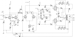
What is the voltage at the cathodes of V2A, V2B (6SN7 pins 3, 6)?
You have a high voltage MOSFET CCS there, which usually needs at least 40Vds to work well. I doubt the 6SN7 is going to have that much voltage from its cathodes to ground. Probably more like 5V, no?
Adding a negative voltage supply to feed the cathodes of V2A/B would solve that problem.
You have a high voltage MOSFET CCS there, which usually needs at least 40Vds to work well. I doubt the 6SN7 is going to have that much voltage from its cathodes to ground. Probably more like 5V, no?
Adding a negative voltage supply to feed the cathodes of V2A/B would solve that problem.
What is the function of the 3 diodes and resistors from each final tube’s anode to ground?
I would add a negative voltage for the the CCS (I use 45 VDC).
Regards, Gerrit
I would add a negative voltage for the the CCS (I use 45 VDC).
Regards, Gerrit
Protection from overload conditions. diodes won´t let saturating plate go below ground so other plate won´t go above 2X +V (see saw action) , under normal (loaded) conditions, diodes will clamp/chop that overshoot.What is the function of the 3 diodes and resistors from each final tube’s anode to ground?
I would add a negative voltage for the the CCS (I use 45 VDC).
Regards, Gerrit
they will also avoid many kV peaks which can and will appear if speaker gets disconnected or is much higher impedance than expected.
I designed this many years ago, I have lost my notes and calculations. I have an Edcor xpwr143 power transformer with 360-70-0-360 volts. Can I assume the 70v bias tap would handle the LTP current if I were to use it for the negative sink on the mosfet?What is the voltage at the cathodes of V2A, V2B (6SN7 pins 3, 6)?
You have a high voltage MOSFET CCS there, which usually needs at least 40Vds to work well. I doubt the 6SN7 is going to have that much voltage from its cathodes to ground. Probably more like 5V, no?
Adding a negative voltage supply to feed the cathodes of V2A/B would solve that problem.
The 70V bias tap is probably not center-tapped, so additional current drawn from that would unbalance the current load on the HV secondary, probably causing at least some core saturation. I'd avoid that.
A small toroid like the Antek AN-0130 should be easy enough to squeeze into the chassis. It measures 2.4" diameter, 1.1" height. 30V 10VA, with two 30V secondaries. Wire the two secondaries in series for 60VAC. The two 6SN7s should draw about 35mA max, which can be easily delivered by the little toroid. It should cost less than $20 shipped in the US.
A small toroid like the Antek AN-0130 should be easy enough to squeeze into the chassis. It measures 2.4" diameter, 1.1" height. 30V 10VA, with two 30V secondaries. Wire the two secondaries in series for 60VAC. The two 6SN7s should draw about 35mA max, which can be easily delivered by the little toroid. It should cost less than $20 shipped in the US.
I think I used this as a model with the css going to ground, and not a neg supply.I designed this many years ago, I have lost my notes and calculations. I have an Edcor xpwr143 power transformer with 360-70-0-360 volts. Can I assume the 70v bias tap would handle the LTP current if I were to use it for the negative sink on the mosfet?
https://www.diyaudio.com/community/attachments/kt88-ul-mullard-draft2-pdf.248747/
also,
"If you use Mullard style topology, you can put an IXYS 10M45S under the LTP's tail, without having to use a negative rail."
Eli Duttman, https://www.diyaudio.com/community/...urrent-sources-under-over-the-triodes.129266/
https://www.diyaudio.com/community/attachments/opus5_0_amp-v15-1-pdf.218569/
Last edited:
I think I used this as a model with the css going to ground, and not a neg supply.
https://www.diyaudio.com/community/attachments/kt88-ul-mullard-draft2-pdf.248747/
also,
"If you use Mullard style topology, you can put an IXYS 10M45S under the LTP's tail, without having to use a negative rail."
Eli Duttman, https://www.diyaudio.com/community/...urrent-sources-under-over-the-triodes.129266/
https://www.diyaudio.com/community/attachments/opus5_0_amp-v15-1-pdf.218569/
Yes, in the "Mullard style topology" the plate of the first stage voltage amplifier is DC coupled to the grid of the driver stage LTP. That puts the LTP's grid at about +100V, so its cathodes will sit up at about +105V or so. That gives plenty of Vds within which the CCS MOSFET can work.
The circuit in post #1 of this thread has the paralleled 12AT7 plates AC coupled to the 6SN7 grid, with C5 blocking DC and R10 as the grid leak for V2A. V2A's grid will be at ground potential (0V) so the V2A/B cathodes will only be up at about +5V (or so).
Thank you very much. Antek sells the an-0130 on Ebay for $16.00 with free shipping. I will do this.Yes, in the "Mullard style topology" the plate of the first stage voltage amplifier is DC coupled to the grid of the driver stage LTP. That puts the LTP's grid at about +100V, so its cathodes will sit up at about +105V or so. That gives plenty of Vds within which the CCS MOSFET can work.
The circuit in post #1 of this thread has the paralleled 12AT7 plates AC coupled to the 6SN7 grid, with C5 blocking DC and R10 as the grid leak for V2A. V2A's grid will be at ground potential (0V) so the V2A/B cathodes will only be up at about +5V (or so).
- Home
- Amplifiers
- Tubes / Valves
- Comment & critique: KT88/KT20 PP UL amp schematic