My last little thing. Before completion.
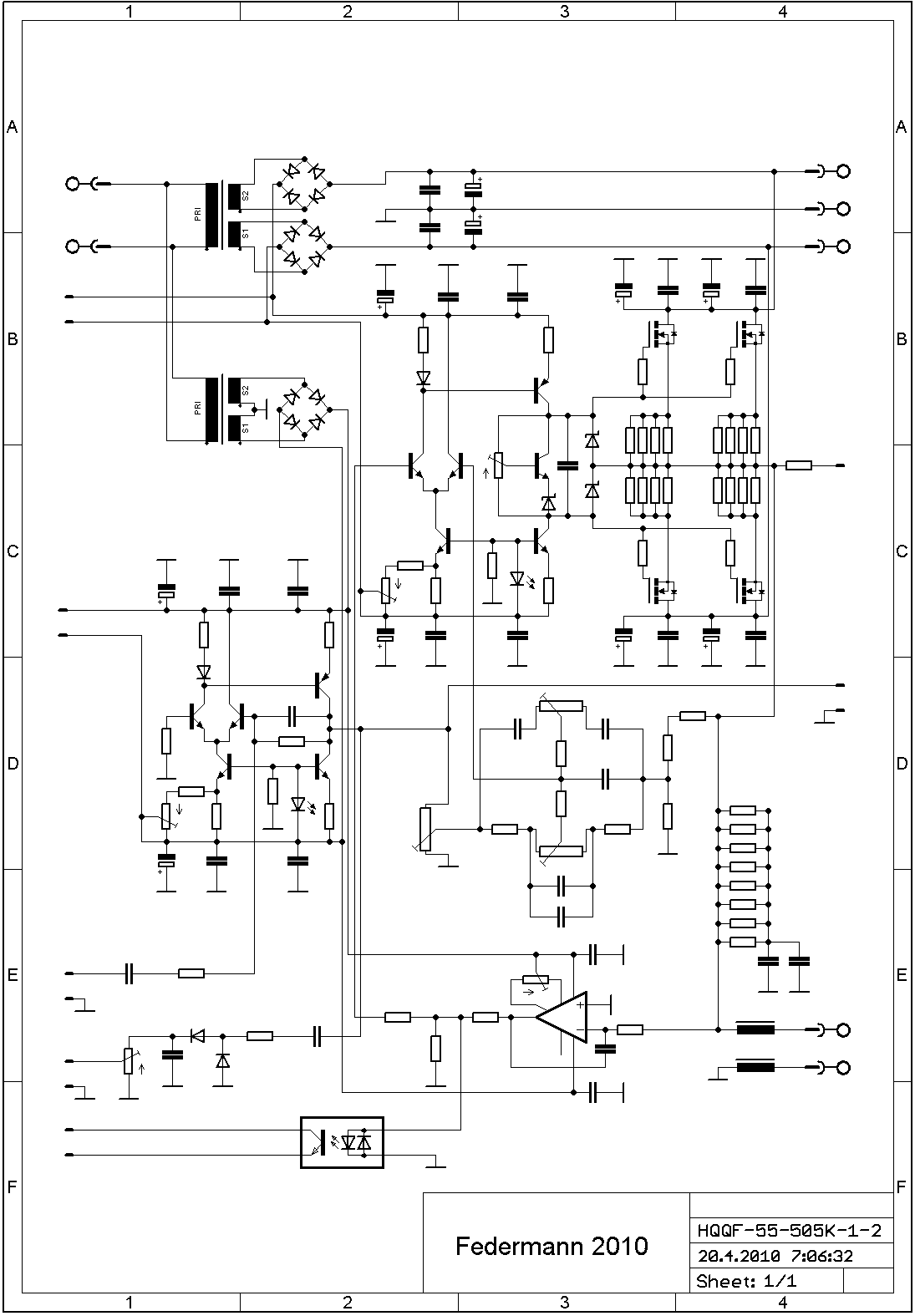
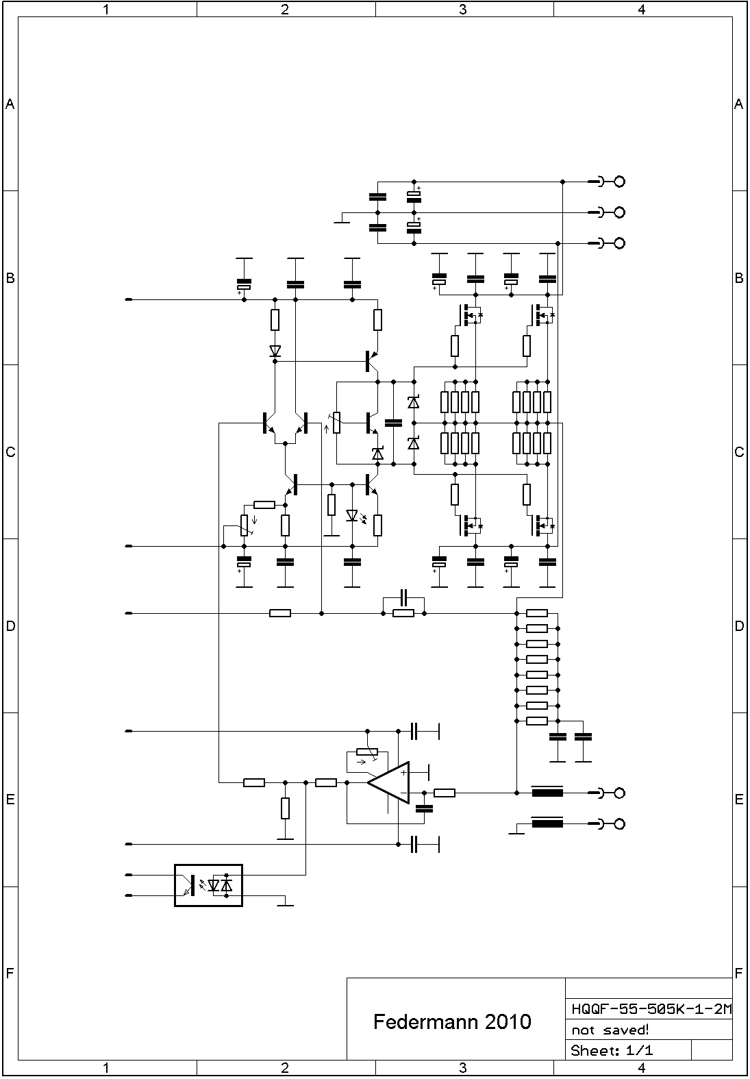
Excuse flawed scheme IRFP9240PbF in Eagle (C3-4), thank you.
An externally hosted image should be here but it was not working when we last tested it.
An externally hosted image should be here but it was not working when we last tested it.
Excuse flawed scheme IRFP9240PbF in Eagle (C3-4), thank you.
Last edited:
500 watts with two pairs of power mosfets ?...
The VAS cant drive directly the mosfets, there
will be much more distorsion that if you add an
emitter follower pair as buffers...
The VAS cant drive directly the mosfets, there
will be much more distorsion that if you add an
emitter follower pair as buffers...
An externally hosted image should be here but it was not working when we last tested it.
An externally hosted image should be here but it was not working when we last tested it.
500 watts with two pairs of power mosfets ?...
The VAS cant drive directly the mosfets, there
will be much more distorsion that if you add an
emitter follower pair as buffers...
2 pairs of only 250W, 500W for the bridge (2+2 pairs).
2 pairs of only 250W, 500W for the bridge (2+2 pairs).
For 250 watts, it s not enough either...
4 pairs is a bare minimum....
For 250 watts, it s not enough either...
4 pairs is a bare minimum....
For 90V output Vp-p (250W/4Ω), just a source of ± 48V. 8Ω bridge.
Hi Federmann,
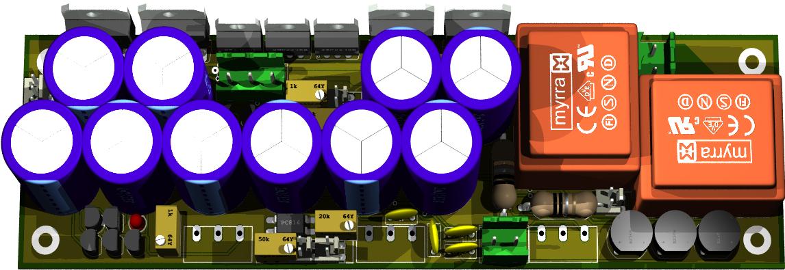
Which EDA/CAD program are you using? Altium Designer is exellent but unfortunately it can't display soldered pads. Solidworks?
Which EDA/CAD program are you using? Altium Designer is exellent but unfortunately it can't display soldered pads. Solidworks?
Hi Federmann,
Which EDA/CAD program are you using? Altium Designer is exellent but unfortunately it can't display soldered pads. Solidworks?
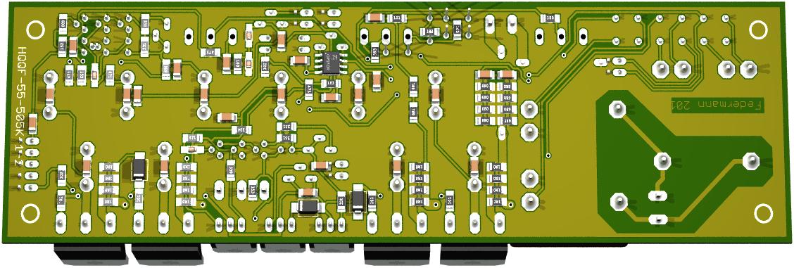
I use EAGLE →Eagle 3D → PovRay. Might help
Hm,
I thought Altium was the only serious 3D PCB EDA developer on the market but looks like Eagle has made a great step in the world of 3D PCB designing. Will try it. Thanks. 🙂
I thought Altium was the only serious 3D PCB EDA developer on the market but looks like Eagle has made a great step in the world of 3D PCB designing. Will try it. Thanks. 🙂
How cooling is resolved? Number of power transistors for 300 watt power does not seem enough. Necessary to compute with the clipping of amplifier. When overloading can crash in power the 100 watts peak rise. What types of transistors, namely the involvement you use? Images are available from the oscilloscope screen? 😉
An externally hosted image should be here but it was not working when we last tested it.
Is it combo like this from your web ? But in this combo you udes tubes, and now you would like to use mosfets. Why did you preferred mosfets contra tubes? I think that soud of tubes has now in rock and country bands such a great credit.
Do you think that it would be better use this model and make another one? I am convinced that this model has outstanding parameters. Can you explain something more about this combo? V, W, inputs for.....phono, micro, guittar...... tone correction...is there line 1,55 output for stereo system used e.g. in Studer A 810 professional Stereo recording tape recorder with speed 19+38+76 cm/s ? This will increase value of combo.
- Status
- Not open for further replies.
- Home
- Amplifiers
- Solid State
- Combo MOSFET 50W÷500W