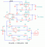
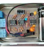
This build is to test the general suitability of 3 components.. TC962, LM317LZ, LM337LZ.. for DIY headphone amps. The boards fits in a single-battery Altoid tin.

The amplifier has two 4556 ICs in parallel. Each section has a modest gain using 1.5k,1.3k feedback and each is decoupled with 1.3R resistors. The TC962 provides the negative rail so that the uncertaintly of virtual ground is avoided.
The TC962 is said to be 97% efficient so yes the negative rail is close to the battery voltage. However, it rolls off significantly with load so regulators are mandatory for balanced opamp rails. The board draws 44ma when idle. I am assuming the inverter uses twice as much as each 4556 so the opamps need about 20ma. That seems to be a comfortable load for the small LM317LZ which is a TO-92 package for upto 100ma.
One disadvantage is the 2v drop across the regulators which limits the opamp rails to +-6v but that is better that the 4.5v in single battery Cmoy with simulated ground. A design using LDOs would provide about +-8vdc.
My only test equipment is a VOM and ATH50 cans. I was expecting some noise with the rough layout, carbon resistors, and junk box caps but found none. Note that the TC962 can switch at 12Khz or 24khz. I used 24khz.

You could prolong your battery life a little by increasing the values of the LM3x7L voltage setting resistors - at present they're sucking around a quarter of your quiescent current.
Significant regulator resistors
Quite right, I did not consider the drain of the regulator resistors. I did not find LDOs I could easily apply. The ones designed for mobile are more efficient.You could prolong your battery life a little by increasing the values of the LM3x7L voltage setting resistors - at present they're sucking around a quarter of your quiescent current.
You could create your own LDO - not quite as low as the latest offerings from the big boys, but still with a shunt reg (LMV431, preferable to TL431 due to lower current operation) and an emitter follower, you can get easily below 1V.
Thanks for the encouragement but I don't have the board space or motivation to do that. But I would be interested in LDO pairs that are not difficult to solder.You could create your own LDO - not quite as low as the latest offerings from the big boys, but still with a shunt reg (LMV431, preferable to TL431 due to lower current operation) and an emitter follower, you can get easily below 1V.
I built a headphone amp with paralleled NJM4556s, basically an O2 design. Didn't like the sound at all, very dull, boring. I have an idea that might fix it up - by bootstrapping the output opamps.
I built a headphone amp with paralleled NJM4556s, basically an O2 design. Didn't like the sound at all, very dull, boring. I have an idea that might fix it up - by bootstrapping the output opamps.
Well, I had a couple of BUF634 but I opted for the 4556s. The point was to investigate power supply options. The amp section was intended to provide a typical load while driving low-Z phones like the ATH50.
I find that dull, boring is good because it means the amp is not coloring the sound. I can tell the difference between headphones but not headphone amps. Assuming the amp has a low output impedance and distortion, the headphone characteristic provides the sound. Opinions vary.
What do you mean bootstrapping. Positive feedback, perhaps?
My use of 'dull, boring' here does not mean lack of colouration, it means the addition of greyness to the sound. Whereas other amps I have add far less greyness - meaning the contrasts in the recording are more evident.
By bootstrapping I meant moving the power supplies up and down in line with the signal. Yes its a form of positive feedback in many implementations though I've also tried it in feedforward.
By bootstrapping I meant moving the power supplies up and down in line with the signal. Yes its a form of positive feedback in many implementations though I've also tried it in feedforward.
Last edited:
Bootstrapping the part of the circuit that supplies all the load current? Eh, I dunno. I mean, it should be doable, that more or less is what Class H is about after all, but it seems a bit messy. I'd much rather bootstrap single opamps that are driving buffer stages on fixed supplies (you pretty much have to do it per channel) - that should require a good bit less current capability and give a higher degree of freedom in design.
Where do you expect "greyness" to show up in measurements? No offense to your audiophile vocabulary but I reckon the chances of it translating to %random_dude_on_the_interwebs% are near zero, and that's definitely a problem on a forum like this. A properly conducted measurement under precisely defined / recorded conditions (circuit, supply, levels, load) may need a somewhat higher degree of interpretation when looked at, but can be fitted into a different frame of reference far more easily. Which, surprise!, is why scientists tend to work like that. Actually even a subjective evaluation may gain a fair bit of meaning if conditions are stated.
I just noticed the OP has individual feedback networks for each paralleled opamp. With some bad luck, this could become a lesson in resistor tolerances. The O2 only gets away with 1 ohm balancing resistors because at the end of the day, the gain of a unity-gain follower tends to be very well-defined. One could probably do worse than checking cross-currents (or cross-voltage-drop for that matter) both in idle and at various amplitudes - since the circuit is DC-coupled, DC should actually do and may be more multimeter-friendly.
Where do you expect "greyness" to show up in measurements?
I'd not expect it to show up in the current suite of measurements. But that's just an indictment of how far measurements reflect what's heard. Its a form of noise modulation so in order to see it I think we'd need a fairly broadband signal (perhaps bandlimited white noise) then put a notch into that and examine the contents of the notch after it has passed through the offending electronics. I've heard such tests termed 'noise loading' but they're not (yet) mainstream.
- Status
- Not open for further replies.
- Home
- Amplifiers
- Headphone Systems
- Cmoy, Charge Pump Inverter, Regulated