Hello everybody,
I've been reading on this forum for a long time but this is my first post.
As you will see, I am not very experienced with Digital Electronic .. please, don't be upset if my question is silly.
I bought the "384kHz Asynchronous USB to I2S/SPDIF CM6631A PCB" from DIYINHK hoping that adding a Coaxial Output was as simple as soldering the connector but it looks like I need a converter circuit. DIYINHK are not very helpful ..
I looked around and have seen that there are some board available with the connector and they use a PE65612NL.
I am wondering if you guys could give me advice on how to do that,
if I need to add any other component to make it work or if there is a better converter.
I am attaching the picture of the board.
Thanks in advance.
blugeco
Attachments
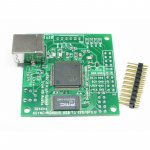
Isn't the unpopulated connector next to the USB port a SPDIF output connector?
The pinout looks like that of an optical connector, but it might take a coax too.
It seems like the traces connect to the general area of the chip with the SPDIF input and output (38-40). Wouldn't cost much to simply solder the connector and see.
I believe the optical connector will require a power supply which is not populated on the PCB though so you might need a little more fiddling. I think the TORX transmitters need 3.3V, so connecting your supply directly to the required pin on the module might do it.
My experience (or someone else's) is that the vendor has basically very little technical knowledge. A unit he bought came with I/V values different from the datasheet but when he asked for the value list he was told they were as per the manufacturer spec. Which they weren't, so it's kind of a stalemate.
bluegco I'm guessing you need something like this to convert the TTL signal to line level.
New SPDIF RCA Out Motherboard Plate Cable Bracket for Asus MSI ECS | eBay
New SPDIF RCA Out Motherboard Plate Cable Bracket for Asus MSI ECS | eBay
- Status
- Not open for further replies.