Does anyone have a Classe Fifteen or has ever drawn an actual schematic of it?
The service manual does not specify which are the low level and river bipolars.
The service manual does not specify which are the low level and river bipolars.
From photos I have seen, apparently Q8 is a TO3 metal transistor, attached with the output transistors on the heatsink.
Q8 is a TO-92 Darlington attached to the main heat sink with blue thermal adhesive.
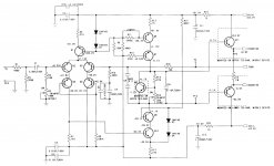
All of the Classe Audio amplifiers of this era share nearly identical front end and output stages. Really all that changes are the main rail voltages and number of output devices. I cannot confirm that these are identical, but here are the parts from the DR-25:
Q1-Q5 2N6519
Q6 MJE350
Q7 MPSA56
Q8 2N6426 Darlington
Q9 MJE340
Q10 MPSA06
Q11-Q15 MJ15024
Lower Devices (PNP, no designators) MJ15025
Thanks, Ungie.
I had taken the parts types from other similar non-fet input series, but the LTPs said 2N5619, which is a TO3 part.
Any idea what the drivers Q11 and below are? They are TO225 or TO220, from the amp photos I've seen.
The Fifteen seemed to be a very good amp, from what I've found out.
I had taken the parts types from other similar non-fet input series, but the LTPs said 2N5619, which is a TO3 part.
Any idea what the drivers Q11 and below are? They are TO225 or TO220, from the amp photos I've seen.
The Fifteen seemed to be a very good amp, from what I've found out.
Thanks, Ungie.
I had taken the parts types from other similar non-fet input series, but the LTPs said 2N5619, which is a TO3 part.
Any idea what the drivers Q11 and below are? They are TO225 or TO220, from the amp photos I've seen.
The Fifteen seemed to be a very good amp, from what I've found out.
The LTP part is a typo on a number of their schematics...it should be 2N6519, NOT 2N5619. The driver is a TO3 part and mounted in the centre of the row of devices on each t-bar of the heatsink. On the DR-25 it is the same part as the output devices. The TO-225 parts you are seeing are part of the VAS and VAS current source, likely the same MJE340/350 parts that are used on the DR-25. They have small heat sinks attached and get VERY hot in the DR-25. In the later Model 25 these parts are mounted to the main heat sink t-bar.
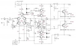
The schematic looks strange on differt places.I tryed to make some sense out of it.Here the result with expected voltages/current indications and transistor proposals.
Mona
The published schematic may look strange, but it matches production units. My DR-25 uses a very similar topology and the device types line up with the DR-15 very closely. Q6 and Q7 look like they are reversed on the schematic, but they are exactly like that on the actual unit. Q8 is a Darlington device.
(Which, as discussed elsewhere, is a pretty major screwup right from the factory. Clearly they didn't do any kind of stress-testing, since like this a failure is a question of when, not if.)Q6 and Q7 look like they are reversed on the schematic, but they are exactly like that on the actual unit.
Last edited:
(Which, as discussed elsewhere, is a pretty major screwup right from the factory.)
Agreed. Do you think it's worth reversing them? I gather the base resistor on Q7 would need to be significantly changed? There is no base resistor on Q6, just a jumper like shown in the DR-15 schematic.
You can't just reverse things.Look at the schematic the changes i made.Agreed. Do you think it's worth reversing them? I gather the base resistor on Q7 would need to be significantly changed? There is no base resistor on Q6, just a jumper like shown in the DR-15 schematic.
What i did at the biascircuit was with a simple transistor, if there is a darlington the original resistor can stay but best with the 100Ω to prevent a very big current in the output stage if, by mistake, the potmeter is turned to zero.
Mona
Definitely, I would hate to operate a ticking timebomb. The parts should swap over just fine since IIRC the PCB footprint is a 2N type for both and the MJE350 is dancing the lead twist right from the factory. Can't hurt to verify connections, of course.Agreed. Do you think it's worth reversing them?
While you have the MPSA56 out, I'd suggest testing it for beta if you can. The part has been seeing excessive voltages and power dissipation and may be substantially degraded as a result. These must be tough as nails to have survived for so long anyway.
No, I think it should work as-is. The base resistor is just for keeping the cascode transistor from oscillating, I guess, and the current source transistor shouldn't need one. Should be fine with the 820R in place... otherwise you know where you could install one.I gather the base resistor on Q7 would need to be significantly changed? There is no base resistor on Q6, just a jumper like shown in the DR-15 schematic.
Doing only one channel at a time, using a bulb tester / variac and having a scope at hand in case there are any problems with oscillation is very much advised, of course, at least in the initial stages until things are proven to be working fine.
The reason I got interested on the Classe Fifteen design is that it resembles very much an amp by Graham Nalty published in UK ETI magazine in the late '80s.
I built two of them, and they stand the pass of time quite well.
Now I think it needs some upgrading, and I thought that I could do some parts changes on it, basing myself on a proven commercial design, the Fifteen, that got good reviews on Stereophile magazine in 2008.
The 2008 version seems to have had some upgradings, according to Stereophile, but I'm not sure what year this service manual belongs to.
My main interest is to get rid of the Darlington drivers, which many people frowned at. And perhaps replacing the output transistors with more modern types, TO3 or TO3P.
Attachments
The schematic looks strange on differt places.I tryed to make some sense out of it.Here the result with expected voltages/current indications and transistor proposals.
Mona
You added a 274K resistor to ground on the LTP cascode bias. I wonder why that resistor is missing in all versions for this schematic
That's a much better design !
Mona
Better than the Classe Fifteen?
Shure, and the Classé 25 and 70 😛Better than the Classe Fifteen?
You now, classé (french) put away for good 😀
Mona
Last edited:
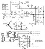
Ketje and sgrossklass, in order to not clutter up this thread, I have published an updated schematic in my original DR-25/Model 25 thread. I would appreciate it if you could both have a look.
Thank you!
http://www.diyaudio.com/forums/solid-state/278883-classe-dr-25-25-repair.html
Thank you!
http://www.diyaudio.com/forums/solid-state/278883-classe-dr-25-25-repair.html
You added a 274K resistor to ground on the LTP cascode bias. I wonder why that resistor is missing in all versions for this schematic
I was wondering that as well. What is the purpose of adding this resistor?
- Status
- Not open for further replies.
- Home
- Amplifiers
- Solid State
- Classe Fifteen transistors