Hello everyone,
This is my first time posting on this forum. Anyway I have to design a discrete class d power amplifier in order to graduate college. I have only modeled the comparator part of the circuit. As can be seen I have built the comparator completely out of MOSFETs because I understand those transistors better than BJTs. My problem is that the input wave forms have to have a DC component in order for the comparator to work. How can I remove this DC component from the inputs and make the comparator work?
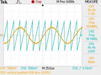
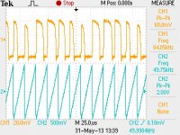
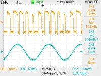
I built the comparator out of ICs (CD 4007) and have attached what I got from the oscilloscope. Again I had to give a DC component to the inputs in order for the comparator to work. I choose ICs just for the purpose of seeing if the circuit would work physically.
Now my next goal is to design the driver stage but I am not sure how to do this. How does the driver stage work and how do I build it?
I have attached the my professor's specifications if that helps.
This is my first time posting on this forum. Anyway I have to design a discrete class d power amplifier in order to graduate college. I have only modeled the comparator part of the circuit. As can be seen I have built the comparator completely out of MOSFETs because I understand those transistors better than BJTs. My problem is that the input wave forms have to have a DC component in order for the comparator to work. How can I remove this DC component from the inputs and make the comparator work?
I built the comparator out of ICs (CD 4007) and have attached what I got from the oscilloscope. Again I had to give a DC component to the inputs in order for the comparator to work. I choose ICs just for the purpose of seeing if the circuit would work physically.
Now my next goal is to design the driver stage but I am not sure how to do this. How does the driver stage work and how do I build it?
I have attached the my professor's specifications if that helps.
Attachments
This is a discrete class d i have derived from reading white papers from hypex and studying the philips UcD circuit: http://i.imgur.com/XEqQBKy.png
Hello everyone,
This is my first time posting on this forum. Anyway I have to design a discrete class d power amplifier in order to graduate college. I have only modeled the comparator part of the circuit. As can be seen I have built the comparator completely out of MOSFETs because I understand those transistors better than BJTs. My problem is that the input wave forms have to have a DC component in order for the comparator to work. How can I remove this DC component from the inputs and make the comparator work?
I built the comparator out of ICs (CD 4007) and have attached what I got from the oscilloscope. Again I had to give a DC component to the inputs in order for the comparator to work. I choose ICs just for the purpose of seeing if the circuit would work physically.
Now my next goal is to design the driver stage but I am not sure how to do this. How does the driver stage work and how do I build it?
I have attached the my professor's specifications if that helps.
Nice project so many solutions so little time.
A good working and most importantly stable circuit can produce up to 200Watts RMS using a UcD modulator (see below) instead of the traditional triangle approach, which by the looks of it you using as shown in your waveforms, also note your reference triangle seems more like a (sawtooth than a triangle) this is no good in fact this looks like a "standard experimental PWM modulator" for motor control.
In the doc specification I don't see any PCB consideration by your professor which should be the first priory how does he/she expect a high speed circuit to produce good results with limited and somewhat nebulous specifications like this.
expect the circuit to produce unexpected results.( A demonstration working design can be archived on breadboard, strip-board with attention to detail especially at the switching nodes)
None the less see this
Discrete Class D High Power Audio Amplifier.
http://www.nxp.com/documents/user_manual/UM10155.pdf
All the best with your design and good luck.
Last edited:
Considering how noisy class D amps can be and how many EMC issues they can create I agree with the above post, PCB is paramount as it is with all switching designs.
Hi Reactance, I have very little experience with regards to class d power amplifiers and pcb boards. I am just trying to build a simple class d power amplifier so that I meet almost all the specifications. I was able to integrate a driver I found on this forum into the previous comparator that I simulated. I was able to get 50 W which is the main specification my professor cares about. Now if I build the circuit in the attached file out of discrete components will it give me similar results as in the simulation?
Attachments
Hi Reactance, I have very little experience with regards to class d power amplifiers and pcb boards. I am just trying to build a simple class d power amplifier so that I meet almost all the specifications. I was able to integrate a driver I found on this forum into the previous comparator that I simulated. I was able to get 50 W which is the main specification my professor cares about. Now if I build the circuit in the attached file out of discrete components will it give me similar results as in the simulation?
If you trying to build a simple amplifier why are you going through all the effort designing one from scratch and going through trial and error experiments with "discrete" comparator, triangle and output stage blocks if the reference UcD circuit i sent you satisfies your professors requirements (100% discrete solution and working ) and as a added bonus it uses a self oscillating so you don't need a triangle as you specified in your simulation and out performs and will probably impress your professor.
There are so many pitfalls with your design, when you move from SPICE to the workbench these pitfalls will unveil.
- Status
- Not open for further replies.
- Home
- Amplifiers
- Class D
- Class D Power Amp (Discrete)