Good day all,
I'm 1 of 5 that is responsible for designing a class d amps for bass frequencies. we got everything to work except the power stage. The output of full bridge configuration outputs a small square wave (mV) from a 5 volts input.
Gate driver: HIP4081a powered by 12 volts
Bootstrap: 10uF and 1N5817
Mosfets: IRFB4019 powered by 24 volts.
Can anyone please assist us?

Above is the schematic. the Uf4007 is not used and the dead-time resistors are 100k. the amplified output is simply measured by placing the oscilloscope probe at the middle of the high side mosfet and the low side mosfets.
It might be a misplaced concern or me being overly cautious but the 1N5817 is only rated to a VRRM of 20V.
https://www.diodes.com/assets/Datasheets/ds23001.pdf
It might seem that during correct operation of your circuit those particular diodes should only see a maximum reverse voltage of 12V but transient conditions might bite you.
It has been suggested in other discussions about the operation of bootstrap drives that using capacitors sized above 1uF can be counter productive. Better to stick to 100n to 1uF and, as per your picture, ideally 100n.
The bootstrap only has to charge the gate capacitance, Ciss, over a single cycle.
https://www.infineon.com/dgdl/irfb4019pbf.pdf?fileId=5546d462533600a40153561587651e03
In this case that's about 1nF, Figure 5) so 100n should be oodles.
Hi Monicaa,
MorbidFractal has some very relevant comments.
Before we start measurements, are the people in the other thread you very recently started concerned with solving the same problem? (it is inconvenient if two threads discuss the same problem simultaneously, then the threads should be merged into one)
If we go on, we have to start with some basic measurements. Diagnostics from just measuring at the final output is not sufficient.
Did you use one of these plastic wire-boards for the test setup?
I see no decoupling on the 12V supply to the HIP4081A. I'd suggest 100nF + 10µF (both ceramic) on the HIP4081A's 12V pin, within 5mm.
The bootstrap caps for the IRFB4019 should be 15nF or 22nF ceramic. They need to hold enough charge to drive the gates. The IRFB4019 gates are 13nC total gate charge, so 15nF will only droop less than a volt charging them and the charge-pump and/or switching keeps them charged.
I've seen people use crazily large bootstrap caps for no reason. BTW you should never add gate pull-down resistors to a circuit like this, a very easy way to cause failures (somewhat counter-intuitive)
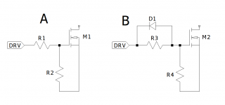
@Mark Tillotson Gate pull down resistors ? The two pull down resistors are to set the dead time or you mean I should have use potentiometers instead?
Last edited:
Sometimes you will see A or B as gate drive connections. R2 or R4 would represent gate pull down resistors. D1 is there to enhance turn off speed. In Drivers like the HIP and others all of this is taken care of by the IC so you only need R1 or R3. These reduce dissipation in the driver and influence parasitic ringing if present. The additional components can interfere with proper operation of the IC.
...
...
Attachments
- Home
- Amplifiers
- Class D
- Class D not amplifying