Here's a simulation of a work in progress class-d design i'm working on...
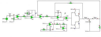
It's pretty rough at the moment & takes an age to simulate, i'm keen to drive the thing directly from rectified mains to loose the big heavy transformer (or separate psu), so i've come up wth this full-bridge design that is at least interesting!
Some of the components are driven out of spec & some are perilously close to spec (i chose components, from the libs shipped with LTspice, for their timings rather than their absolute voltage & current ratings)
here's the simulation LTspice simulation
the lack of discrete capacitors has me worried....
Be as critical as possible
cheers
Rob
It's pretty rough at the moment & takes an age to simulate, i'm keen to drive the thing directly from rectified mains to loose the big heavy transformer (or separate psu), so i've come up wth this full-bridge design that is at least interesting!
Some of the components are driven out of spec & some are perilously close to spec (i chose components, from the libs shipped with LTspice, for their timings rather than their absolute voltage & current ratings)
An externally hosted image should be here but it was not working when we last tested it.
here's the simulation LTspice simulation
the lack of discrete capacitors has me worried....
Be as critical as possible
cheers
Rob
Attachments
Well, for starters you'll have much higher than 120Vdc if you rectify 120Vac mains. Your supply rail would be more like 168Vdc and would fluctuate as mains voltage isn't always stable. I now see you simulated the mains voltage but have it labeled 110 and 120. You should change the labels and be sure to spec the parts for the higher voltages.
Other than that, you'll need freewheeling diodes across the output mosfets to conduct the inductor current during the dead time or you'll be replacing a lot of output mosfets. I don't know enough about the rest of the circuit to make any other suggestions, except to maybe use small resistors in series with the gates of the pnp driver bjt's to ensure current sharing?
Other than that, you'll need freewheeling diodes across the output mosfets to conduct the inductor current during the dead time or you'll be replacing a lot of output mosfets. I don't know enough about the rest of the circuit to make any other suggestions, except to maybe use small resistors in series with the gates of the pnp driver bjt's to ensure current sharing?
Interesting. Why the bridged design? Is it so you can use a single 120V rail? As BWRX says, you'll get a lot more than 120V after retification. And you'll get some pretty big voltage swings if you don't regulate or use massive filter caps.
Nice simple design. How well do you think the oscillator circuit will work?
Nice simple design. How well do you think the oscillator circuit will work?
Hi buddy,
Be careful with directly rectified from mains.
Please pay attention that the speaker is not designed for connected directly to mains. Why? If you get your speaker blown or melted, the coil is very easy to meet the body of your speaker. Then you have speaker body connnected to mains. And if your speaker box is not so dry enough.... very dangerous!
Please use 35mA MCB with ground fault protection when you will play with mains. But it is still dangerous too..! You still have electric current flow accross your body....ie hand to hand with your hearts in between.
Please make sure what you are doing with mains....
br/tn
@BWRX: Good point about it not being the ac voltage, doh! The circuit here is very badly labelled & specced, more a proof of concept than something to be commited to reality! I'll add the diodes, essential 😉 balancing resisitors too (& other niceties like decoupling the input, for the final design) I would like to be able to parallel the mosfets too, so that will require more balancing too, probably requiring separate drive circuits for each mosfet?
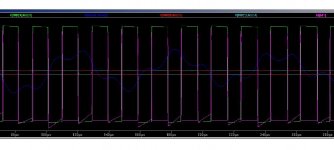
@tim_x: ltspice reckons nothing untoward at power-up assuming the power supply ramps up smoothly, the biggest worry is the cross conduction thru both mosfets at crossover, the simulation gets peaks of >200A, i hope cabling resistances & the PSU will control this. Maybe i could add some x-over delays too? The mosfets chosen are way underspecced but seemed an OK choice to get the simulation up & running.
@panomaniac: The full bridge design is specifically so that i can use a single rail, however i'm getting more tempted to add a PSU to produce a balanced regulated supply.. It might be that the extra (and fairly high spec) components needed for a mains rail PSU (and other problems) will justify a separate PSU, especially if i use an SMPS.
The oscillator is pretty triangular (using these opamps, i chose them as they seem to be pretty generic ultra-high speed types) I almost treat op-amps as discrete components 😉 In ltspice it looks OK at 1/2Mhz, with the RC's here it's only running at 50Khz, enough for bass usage.
@kartino: I'm living in country where it's a good day if you get less than 3 phases thru u when working near electrical equipment! Almost everywhere lacks a ground lead so having mutually grounded equipment can be more hazardous as leakage in one piece of equipment will electrify everything! I've learnt to wear rubber gloves & disconnect absolutely *everything* before doing work now!
I installed ELCB's on alot of the audio equipment here & couldn't get the damn things to stop cutting out! Fortunately the speakers themselves are all hidden out of reach inside wooden boxes as they are all horn loaded! I think the dangers of live speakers are evident even without a direct mains supply as most PA amplifiers are capable of producing well over 100v P-P.
cheers,
Rob
Hi,
From simulation it looked that you need to improve your gate driver. It looked that your gate driver need faster and need delay. You see that there are hundreds amps crossing yous end fets.
Your gate also already start to ON before the opposite became OFF. That is beause you don't have charging delay or your gate too slow to discharge.
Your gate driver supply for low side still 120V, wow... are you sure???
Another, you need are floating ground like felix's for your input stage, isn't?
Also looked that you have problem with communication between input stage and gate driver, level shifter problem. In my opinion it shall have difference circuit between high and low side gate driver to make good connection with input stage.
Please see UCD based in this forum, on eof Chris's (classd4sure) is full bridge. But still need groud reference.
Good luck,
kartino
Attachments
Hi Rob,
From 120VAC with just a bridge and a single 250µF cap feeding a 100V switching regulator you can get 600W/8R from a handful of inexpensive parts.
T.I. makes a 1.7W PWM amplifier with THD rated at 0.0018% @1Khz that runs on 5V (TPA6204A1).
Using two pair of IRFP9140/140 and the above T.I. chip as a driver you're in business.
The T.I. part is about $0.50 in 1K lot, the IRF parts about $1 each or so.
With paralleled outputs for the P-channel parts, power can be up to 2KW or so at 2R. There are N-channel parts available that are heavy enough to not need paralleling.
I can surface mail someone a conceptual schematic (amp only, not the regulator) for scan and posting purposes.
@kartino: yep i do need to look at the high current at crossover, i think a delay is the best thing here. The low-side driver was simply copied from the high-side for the sake of it! It shouldn't require a higher rail to switch, i made the high & low side drivers identical to (hopefully) extract identical performance from all the mosfets.
The level shifter is a bit simple too, but maybe it'll be OK!
The input stage requires a balanced supply too. The extra low power DC supplies will already be available from other circuitry that would be bundled inside the same case as the amp.
I think i need to look at alot more designs before i carry on with mine!
@djk: I've been looking for suitable integrated pwm amplifiers (there are too many damn IC's nowadays!), this one looks good, do u think it would work well down to 20hz? It seems to have been designed with mobile use in mind so maybe it has a fairly high low-frequency roll-off (i guess this would depend mainly on the circuitry to drive the chip.)
I feel like i'm reinventing the wheel designing my own class-d & my wheel is not getting particularly circular!
cheers
Rob
Smart thinking there, DJK!
I remember my first experiances with power switching, I was boosting the power handling of remote control cars to use much larger motors. Mostly I just burned up MOSFETs.
Getting it right is important, the output devices are easy to kill. (I never did get it right, but there was no www to help, back then.)
The device I listed is the lowest distortion one. It may be better to pick the one with the lowest switching frequency, even if higher distortion. They have a bunch to choose from.
oldroborg said:@kartino: yep i do need to look at the high current at crossover, i think a delay is the best thing here. The low-side driver was simply copied from the high-side for the sake of it! It shouldn't require a higher rail to switch, i made the high & low side drivers identical to (hopefully) extract identical performance from all the mosfets.
The level shifter is a bit simple too, but maybe it'll be OK!
The input stage requires a balanced supply too. The extra low power DC supplies will already be available from other circuitry that would be bundled inside the same case as the amp.
I think i need to look at alot more designs before i carry on with mine!
@djk: I've been looking for suitable integrated pwm amplifiers (there are too many damn IC's nowadays!), this one looks good, do u think it would work well down to 20hz? It seems to have been designed with mobile use in mind so maybe it has a fairly high low-frequency roll-off (i guess this would depend mainly on the circuitry to drive the chip.)
I feel like i'm reinventing the wheel designing my own class-d & my wheel is not getting particularly circular!
cheers
Rob
Hi Rob.
I've played with your circuit a few days ago, didn't really like it.
In your above post you've very clearly summed up all the advice I had which I neglected to post, so yeah I second what you just said.
A few other things I had to say was I dont' think extra delay will be enough to save this. Your signals are brutally overlapping, you need tight control over the switch points to avoid that, with extra fine tuning capabilities for slew control over Vgs, where turn on needs to be about twice as slow as turn off. That's your gate resistor as one possibility. ESR and ESL wont' cut it there.
I'd urge you to do more research but also actually try out a few other known to work designs that you can build at "low power", say 50 to 100W, for a safe way to learn exactly what makes a mosfet tick.
Still it was unique and not half bad, great try, keep at it, you'll gain the understanding required over mosfets as you go, takes time and alot of research though.
Regards,
Chris
You're right Chris, It is just about mosfet. I just also new in how mosfet works. Although so simple in ear, but it is became so complicated when works with hi frequency, because they need to charged and discharged in nano seconds.
Even BJTs that shall to be considered to that every BJT also have capacitance, because this class D area is hi freq area.
That simple word for me hi freq mean careful in capacitance, thinks how small resistor, think how fast the switch, simulate it, then get the result what happen from the simulation.
Good luck Oldroborg.
i just built a smaller version of that circuit that, It will sound very bad with a lot of distortion. You NEED to have some negative feed back for the circuit to work correctly as the op amps are not linear at that frequency. After i put feedback on my circuit it sounded good on the full audio range even with a 100KHz sampling frequency.
Here is my circuit:
Here is my circuit:
Attachments
i would say that i is very important to have a good amount of negitve feedback from the output back to the input. This is for two purposes,
1. The output can quite easily have a DC offset negative feedback would prevent this.
2. Op amps are not perfect at that frequency and will give a slighly distorted square wave and triangle wave. Negative feed back would reduce the affect of this on the output.
There are two ways in which you can do this, One is by taking the output after the LP filter and using an opamp to feed it back to reduce the output.
The second is to use a ramp generator before the comparitor and feed the square wave output back into that via a resistor.
or both!
also your supply rails are far two high and the chances are that the whole thing would just go bang and destroy the speakers that are attached to it.
bob123 said:i just built a smaller version of that circuit that, It will sound very bad with a lot of distortion. You NEED to have some negative feed back for the circuit to work correctly as the op amps are not linear at that frequency. After i put feedback on my circuit it sounded good on the full audio range even with a 100KHz sampling frequency.
Here is my circuit:
once i solve the other problems like the incessant shootthru 😱 i'll add these to the ever growing list of things to check! I'm anticipating using very low switching frequencies & minimal distortion is not so important. DC offset is though! I'm beginning to reckon the rails are probably too high aswell, probably much better off building more than 1 lower rated amplifier rather than putting all my eggs in one basket. The speakers should be able to withstand mains directly (for a short while 😀 ) but not rectified though!
darkfenriz said:How about such modification for adjustable dead time:
yep, i've played with adding a small dead time, i added another opamp with a similar config (your circuit saves the opamp 😉
just out of interest what op amps are you using as i have found it is very difficult to get opamps with a half decent slew rate for class d amplifiers?
- Status
- Not open for further replies.
- Home
- Amplifiers
- Class D
- class d design