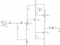
Just thought I'd throw this little circuit over here for the tube guys and gals to have a look at. It is just a work in progress and none of the values are optimum but it does work as I am listening to it now. I will later build a better unit with ccs's and higher voltage for more power but as this circuit is it puts out a very nice sounding 5 watts.
Attachments
A FIWA 😀
Bipolar's are finicky little guys, but don't to too bad once you get them going right. Should be a good project!
Bipolar's are finicky little guys, but don't to too bad once you get them going right. Should be a good project!
 reality warning
smoking-amp said:12AU7 at 15 Volts B+ !!
What kind of distortion levels is this producing?
By the way. I don't mean this kid's project. He will defenitely learn a lot, at least he don't hesitate to think and create. Now he needs to learn how to evaluate.
I what to tell you that 12AX7 works really well at 15 Volts B+. A first, I used it in microphone amplifiers. And second, I use them in my receiver, it is miliraty beast Collins R-392 with 28V B+.
"to tell you that 12AX7 works really well at 15 Volts B+. "
Umm..., well, for microphone signal levels this could be OK since the signal voltage level is so tiny it would not see much curvature in the tube response.
The RF stage in the Collins would put 2nd harmonic and above outside the IF bandpass, so is safe.
But for an audio power amplifier, one will hear large signal tube curvature distortion up to many harmonics. Maybe could get away with this low B+ by using a more suitable low voltage tube like 6GM8 or some of the car radio tubes.
Don
I agree that the 6GM8 is a MUCH better choice for a LOW voltage situation.
Using the "sand" only for current amplification is THE proper choice. Paired with EFFICIENT speakers to avoid clipping, a refined version of the design will sound DECENT.
Using the "sand" only for current amplification is THE proper choice. Paired with EFFICIENT speakers to avoid clipping, a refined version of the design will sound DECENT.
Always have to bust my chops eh tschrama lol. The circuit works just fine, as I said the first schematic was just a test build to check some theory. Since it worked out I went ahead and built a little better version. As for using the 12au7, I had one laying around collecting dust as I usually only work with bjts, a different may work considerably better. So here is the new build.
Attachments
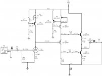
Nice touch with the current source loads. But it appears that the 12AU7 still only has 40 milliVolts of bias headroom between grid and cathode. Will be entering A2 grid current region with 1V input signal, causing significant distortion. Needs more plate current and higher grid bias. You'll need more B+ on a 12AU7 to get the plate current. Try a 6GM8 tube or maybe a high gm tube like 6DJ8.
Don
Don
jerluwoo said:Always have to bust my chops eh tschrama lol. The circuit works just fine, as I said the first schematic was just a test build to check some theory. Since it worked out I went ahead and built a little better version. As for using the 12au7, I had one laying around collecting dust as I usually only work with bjts, a different may work considerably better. So here is the new build.
I'd not modulate Q2's base current. Try it as a CCS.
smoking-amp said:"to tell you that 12AX7 works really well at 15 Volts B+. "
The RF stage in the Collins would put 2nd harmonic and above outside the IF bandpass, so is safe.
Don
No, Collins used them for AF asmplifications and for diodes. For IF they used 6BA6 version with 26V filament.
For AF output they used 26A7 double triode.
Using Q2 as a ccs puts the output stage in single ended mode which requires twice the idle current for the same power. As it is now the output is working in push-pull which is considerably more efficient.
jerluwoo said:Using Q2 as a ccs puts the output stage in single ended mode which requires twice the idle current for the same power. As it is now the output is working in push-pull which is considerably more efficient.
You mean, "semi-push-pull"? 😉
No I do mean push pull. Me and tschrama had this discussion over in the ss forum about this output stage. The ac current supplied by both output trans. are even ie. each supplies half the ac curent that is flowing through the load.
jerluwoo said:No I do mean push pull. Me and tschrama had this discussion over in the ss forum about this output stage. The ac current supplied by both output trans. are even ie. each supplies half the ac curent that is flowing through the load.
It is a magical miracle. 😉
Definitely needs a higher B+ and hence capacitor coupling to the BJT output stage. Also preferably something with a higher gain than a TIPxx in the driver/phase splitter stage.
As it is now, there is a considerable lack of output swing (hence far lower efficiency than possible), and it is also highly non-symetric. It would be prudent to check clipping conditions, and judgeing from the symbols used in the schematic, not to trust the default model for the AU7 triode in Circuitmaker because it has paifully little in common with the real world AU7 especially at low currents. Perhaps a voltage doubler for the tube B+ (would give you 80V) and use a 6DJ8, maybe even both sections in parallel (each section has it's own cathode resistor).
As for 'it works'... I am sure sound comes out if you connect a speaker, but the devil is in all those details...
Swapped for a 6j6 found late last night. Definately more clarity from this tube and it works well in both the 15 and 40 volt versions of the circuit.
Yes I completely agree that the transistors I'm using are crap but I get them fairly cheap 10 mins from home so they are what I use to "play" with. There are huge gains to using better mje transistors in this circuit. Anyone know where to get tube models that will work with circuitmaker? All that I have found give errors when you try to sim.This circuit also works when built under multisim 8 measuring about 1.3% thd at 18 watts. Both sims give nearly identical results bias current and voltage.
If I understand loadlines correctly (if as I never tryed anything with a tube until a couple days ago) the optimum grid bias for both the 12au7 and 6j6 falls at 0 volts or very close for these small voltage and current. That is if I'm correct in thinking that grid voltage is based on cathode voltage (for instance voltage of grid is +1 or -1 above or below cathode voltage for bias setting).
I recommend building the simple 15volt version to see how well it works. Will have to figure new load resistor for tube and bootstrap current for your transistors if you use different. My outputs are mje3055t's and require a large amount of bias current for decent output current.
Hi Jerluwoo, sorry for being so sceptical .. I wrongly assumed you only simulated it, and not really build it.. but you must agree that your circuit looks unrealistic and I was a bit surprised to read from you that is actually works...
How about a Jfet for the tube ?
So how about some THD versus output Vac measurements of the tube driver only... I cann't see a problems with the output stage ... but is you biasing constant,.. any turn-on dump..?
How about a Jfet for the tube ?
So how about some THD versus output Vac measurements of the tube driver only... I cann't see a problems with the output stage ... but is you biasing constant,.. any turn-on dump..?
I was warned in another thread not to use a direct coupled tube ro transistors,thats why I´m interested how it works..... but is you biasing constant,.. any turn-on dump..?
Then it is not an hybrid..😎 🙂How about a Jfet for the tube ?
- Status
- Not open for further replies.
- Home
- Amplifiers
- Tubes / Valves
- Class A Tube BJT Hybrid