Hi all,
I'm designing my own 30W class A amplifier or at least trying to do it....😀
At the moment I decided to use Class A CFP as reported on Douglas Self book.
At first I tought to use a current mirror topology and a cascode buffered vas. I tried to implement it but my need of low closed loop gain leads me to have an amplifier with more than 100dB of feedback. This cause me to great problems in compensation and looking for stability.
Now I decided, at opposite, that I will try to have a very linear open loop amplifier and then apply feedback. At the moment I'm using a differential VAS and in this way I can get a closed loop thd20 of about 3e-3 prior to clipping and this quite satisfies me. Do you have some advices on differential VAS since its the first time I use it?
Thanks,
Michele
Attachments
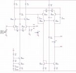
Hi,
The second version I posted has 70dB open loop gain as opposed to the first version, not reported here that has 130dB open loop gain so I have reduced OLgain of a great amount. I was only looking for an advice about differential vas or better topologies if anyone knows.
Thanks,
Michele
The second version I posted has 70dB open loop gain as opposed to the first version, not reported here that has 130dB open loop gain so I have reduced OLgain of a great amount. I was only looking for an advice about differential vas or better topologies if anyone knows.
Thanks,
Michele
Hi,
the cascode diodes are upside down. They pass in the forward direction to generate Vf.
What current does the j503 pass?
the cascode diodes are upside down. They pass in the forward direction to generate Vf.
What current does the j503 pass?
Hi,
Unfortunately my own version of spice does not have differences in symbol for normal diodes and zener ones. The diodes you see are zener so they're inverse biased to generate Vz. J503 is a CR diode for about 0.55-0.6mA.
Thanks,
Michele
Unfortunately my own version of spice does not have differences in symbol for normal diodes and zener ones. The diodes you see are zener so they're inverse biased to generate Vz. J503 is a CR diode for about 0.55-0.6mA.
Thanks,
Michele
Hi,
you might be better using red LED or two for the diode cascode voltage, rather than a Zener.
The CCS to the ltp is sourcing about 6mA. Take off the 0.6mA of the Zener and 2.7mA is passing each collector load.
Is ~4V across these loads what you intended?
you might be better using red LED or two for the diode cascode voltage, rather than a Zener.
The CCS to the ltp is sourcing about 6mA. Take off the 0.6mA of the Zener and 2.7mA is passing each collector load.
Is ~4V across these loads what you intended?
Hi,
Thanks, I will try to use LED instead of zeners. I planned to leave 4 volts over the load resistor since the voltage swing there is not great and also because in origin I planned to use a cascode CCS also under the differential VAS. Is it worth?
Michele
Thanks, I will try to use LED instead of zeners. I planned to leave 4 volts over the load resistor since the voltage swing there is not great and also because in origin I planned to use a cascode CCS also under the differential VAS. Is it worth?
Michele
have you checked the currents in the VAS?m_buzzi said:I planned to leave 4 volts over the load resistor
Hi,
4.962mA in the side connected to output stage opposed to 4.815mA in the other side. This seems to me quite reasonable. Isn't it? Note that the output stage has a predriver and so current requirements to VAS are really low.
Michele
4.962mA in the side connected to output stage opposed to 4.815mA in the other side. This seems to me quite reasonable. Isn't it? Note that the output stage has a predriver and so current requirements to VAS are really low.
Michele
I think VAS currents are over 6mA.
But even 5mA is a lot of dissipation for 550/560 To92 devices.
But even 5mA is a lot of dissipation for 550/560 To92 devices.
Do not drive base of any cascode devices from low impedance source or use 10...22 ohm basestopper resistors.
Hi,
That's right Q11 and Q12 are dissipating about 120mW. This seems too much also for me. I will change them with a more aggressive type.
For VAS current around 5 mA is what my calculation shows. LTP is biased something around 5 mA (Ic=(1.2-0.67)/Re), subtracting 0.56mA for J503 remains 2.25mA on 1.5k that makes up 3.4 volts over the load resistor. Substituting in the equation for DC bias of the differential VAS you will find a current of about 5 mA.
EDIT: Now trying to add base stopper
Thanks
Michele
Hi all,
I tried to substitute the transistor with more aggressive type and the performance remains the same, that's great. The 22R ohm resistor for base stopper lead to a little higher distortion 3.3e-3 instead of 3e-3 but seems safe to use it.
I was thinking if I can improve that data improving the quality of the differential vas. Is there something I can do??
Thanks,
Michele
Hello Michele,
remember to post regularly an updated schematic of your work.
What about common mode feedback from the differential VAS to the CCS in the front-end? Take a look here.
http://www.cordellaudio.com/poweramp/mosfet.shtml
remember to post regularly an updated schematic of your work.
What about common mode feedback from the differential VAS to the CCS in the front-end? Take a look here.
http://www.cordellaudio.com/poweramp/mosfet.shtml
- Status
- Not open for further replies.
- Home
- Amplifiers
- Solid State
- Class A Design in progress