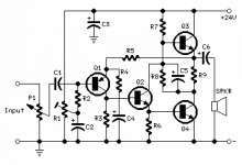
This is Flavio Dellpiane's version of Class A - 7W. Every sensible ear longs for one to build. I prefer this one to Jean Hiraga's or Nelson Pass' as it is less frightening for a first timer! No FET, no toroid or big capacitor, at-least what it promises. I just need the best pcb layout for the schematic. I'm not very good at simulation software, though I tried few times.
7 Watt Class-A Audio Amplifier - RED - Page177
7 Watt Class-A Audio Amplifier - RED - Page177
Attachments
Last edited:
but keep in mind, the other designs you mention have known good PCBs available and have been built by MANY others.
these are two features that are important for mitigating risk for new builders.
if you are not willing to make the pcb yourself, think carefully before deciding ....
mlloyd1
these are two features that are important for mitigating risk for new builders.
if you are not willing to make the pcb yourself, think carefully before deciding ....
mlloyd1
Bipolar transistors are a very poor choice for Class-A amplifier output stages because of their tendency to run away and suffer from secondary breakdown, hotspotting and gm-doubling. MOSFETs are immune to all of these and their lower inherent gain makes them less suitable for Class-AB output stages, but almost perfect for Class A operation.
You can check out juma's variation on the F5, which uses bipolar input pair instead of the JFETs, and the outputs are MOSFETs. It is sonically very similar to the F5 and measures almost exactly the same. I have built one of these and am very happy, as long as good components are used.
As to the toroid, I have run these amps off commercial grade SMPS and laptop supplies, EI transformers also work well if they are properly rated, so that bit is up to you. Big capacitors in the supply are to keep the 50Hz noise down due to the poor PSRR of simple designs, a trait which the design you posted shares. You willlneed a quiet supply. SMPS need relatively little capacitor support because the 50Hz noise is inherently lower.
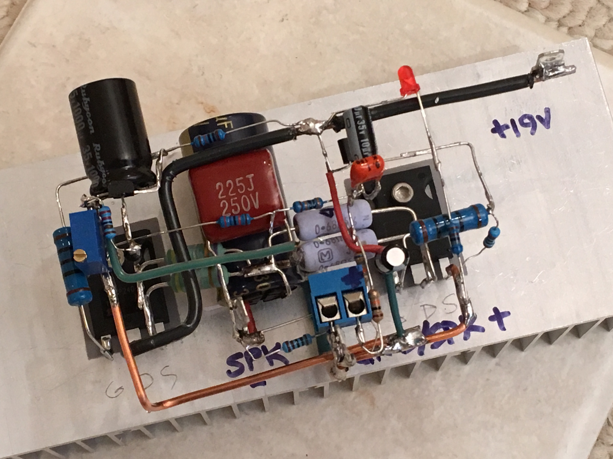
I had created a PCB that accepts both the JFETs as per the original F5 design, as well as the variation by juma - and work with the very oddly shaped heatsinks usually available in India. Fans are required on some sinks - but it was possible to achieve very low costs for building an amp based on this kind of circuit. Some pictures are attached, this build used the input JFET but you can see the RC combination for the bipolar input. Sorry I have none left. But it is possible to wire these up P2P, they are that simple.
You can check out juma's variation on the F5, which uses bipolar input pair instead of the JFETs, and the outputs are MOSFETs. It is sonically very similar to the F5 and measures almost exactly the same. I have built one of these and am very happy, as long as good components are used.
As to the toroid, I have run these amps off commercial grade SMPS and laptop supplies, EI transformers also work well if they are properly rated, so that bit is up to you. Big capacitors in the supply are to keep the 50Hz noise down due to the poor PSRR of simple designs, a trait which the design you posted shares. You willlneed a quiet supply. SMPS need relatively little capacitor support because the 50Hz noise is inherently lower.
I had created a PCB that accepts both the JFETs as per the original F5 design, as well as the variation by juma - and work with the very oddly shaped heatsinks usually available in India. Fans are required on some sinks - but it was possible to achieve very low costs for building an amp based on this kind of circuit. Some pictures are attached, this build used the input JFET but you can see the RC combination for the bipolar input. Sorry I have none left. But it is possible to wire these up P2P, they are that simple.
Attachments
Rubbish !Bipolar transistors are a very poor choice for Class-A amplifier output stages because of their tendency to run away and suffer from secondary breakdown, hotspotting and gm-doubling. MOSFETs are immune to all of these and their lower inherent gain makes them less suitable for Class-AB output stages, but almost perfect for Class A operation.................
ClassA with BJT output stages is perfectly possible.
ClassA with mosFET output stages is perfectly possible.
Both Vertical mosFETs and BJT output stages need temperature compensation to maintain a safe and consistent level of output bias current. Both styles will suffer increasing current at higher temperatures, if built incorrectly.
If one wants to use Lateral mosFETs for the output stage, then these are inherently temperature stable and can operate without a temperature compensator.
Look up the jlh 10W design.This is Flavio Dellano's version of Class A - 7W. Every sensible ear longs for one to build. I prefer this one to Jean Hiraga's or Nelson Pass' as it is less frightening for a first timer! No FET, no toroid or big capacitor, at-least what it promises. I just need the best pcb layout for the schematic. I'm not very good at simulation software, though I tried few times.
7 Watt Class-A Audio Amplifier - RED - Page177
There are some higher power versions of this if you want more later.
The Class-A Amplifier Site
Rubbish !
ClassA with BJT output stages is perfectly possible.
ClassA with mosFET output stages is perfectly possible.
Both Vertical mosFETs and BJT output stages need temperature compensation to maintain a safe and consistent level of output bias current. Both styles will suffer increasing current at higher temperatures, if built incorrectly.
If one wants to use Lateral mosFETs for the output stage, then these are inherently temperature stable and can operate without a temperature compensator.
Vitriol much, Mt. T?
The fact remains that bipolars suffer from gm-doubling distortion when run at very high bias currents. The fact remains is that they are susceptible to secondary breakdown at these currents. Or are these rubbish too? Is everything that does not conform to your view rubbish? Is proven and documented work (Cordell comes to mind) rubbish? Who are you to rubbish all of this?
The fact also remains that almost every design using bipolars and a Class-A or high bias output stage favours using multiple pairs in parallel at very low individual pair current to get around these issues. The fact also remains that no single modern Class-A amp (if any) uses individual pairs of bipolars at large currents. The fact remains that all these designs date from the 60s and 70s, when MOSFETs were in their infancy and not developed to the level that they are today. Or, is that rubbish too?
You can do anything you want and believe it is perfectly possible, but just because you can does not mean you should.
As usual, it has to come down to this. And this is the last time. Ignore listed.
Ok, fellows, peace. Thanks for all your thoughts. Though it happens to go overboard sometimes for all of us while in an argumentative discussion, but lets not cross the line. None or nothing is rubbish in this nice world, everything has two or more sides. Scotoma is a great word, with roots in Greek philosophy, that says, we see what we want to see. So if we want to see BJT performing well within our need, its fine. So are MosFETs. Let me clear my choice of this design. There are so many Class A designs from many big, old and reputed names. But choice of Class A is definitely not for power, or quantity. Its about quality, something we miss in today's world. And 7W from a Class A is definitely not at par with 7W from a Class AB. In old times 230v DC at rail was norm, so were the tubes. Its hardly thinkable mainstream now, at least at affordable cost. The guy made a 3-5W Class A many years back with some accolades from similar enthusiasts, who might look elsewhere other than JLH's '69 design and got featured in AudioXpress mag, trying to resurrect the old tube feel. And not just me, but many crave for Italian designs, that says elegance in simplicity, just like French wine or Swiss Precision. Its about age old philosophy. Yes scotoma, again! Remember Bruno Murari, who invented TDA 2002, later 2003 for STM? The technology was available to all, so why others could not come with that amazing piece of IC? In fact I still make alternate designs with 2003 and little tinkering yields amazing results with proper drivers for a medium room. And different genres respond differently. The guy at redcircuits makes designs for simple minded fellows who put much of their enthusiasm for the music itself while keeping the basics at their best possible level. And he has made many more audio circuits and must have met the issues mentioned here. Below are some links from the site. This thread is going interesting, though I just needed a PCB or strip-board layout!
3 - 5 Watt Class-A Audio Amplifier - RED - Page80
Miniature Class A Amplifier
3 - 5 Watt Class-A Audio Amplifier - RED - Page80
Miniature Class A Amplifier
Last edited:
For low power this amplifier by lineup is a good candidate.
http://www.diyaudio.com/forums/soli...t-no-feedback-simple-circuit-great-sound.html
http://www.diyaudio.com/forums/soli...t-no-feedback-simple-circuit-great-sound.html
This is Flavio Dellpiane's version of Class A - 7W. Every sensible ear longs for one to build. I prefer this one to Jean Hiraga's or Nelson Pass' as it is less frightening for a first timer! No FET, no toroid or big capacitor, at-least what it promises. I just need the best pcb layout for the schematic. I'm not very good at simulation software, though I tried few times.
7 Watt Class-A Audio Amplifier - RED - Page177
You could build this on veroboard the way the circuit is laid out. It is just a matter of correctly spacing the pins in the matrix to take the components - and use hook up wire to join these as required.
This was the method used by Linsley-Hood for his simple Class A amplifier - the power transistors were mounted on heat sinks with flying leads to the board. This amplifier is similarly simple.
If you want a pcb you could follow this general practice by drawing the layout on graph paper and glue (diluted PVA) to the top side of a blank board - then drill out the holes and draw the connecting traces on the copper side.
It helps to have a scrap piece of wood behind the copper when drilling - to make it easier to smooth the hole edges on that side.
The earth connection should be at the input end of the board. The other thing to do is to have the output leads/terminals and power transformer as far away from the input leads as possible.
I have built the Pass ACA as point to point with no PCB. It is perfectly suitable for this and sounds great. I use a 19v SMPS and a tiny heat sink with a small speed reduced fan (silent) so the whole thing is small and easy to use anywhere. I like the sound of MOSFETs.
There is no thermal compensation on ACA because the output MOSFETs have more capability than the SMPS. It simply can't burn out.
You might want to give it a try.
There is no thermal compensation on ACA because the output MOSFETs have more capability than the SMPS. It simply can't burn out.
You might want to give it a try.
There are numerous Class A designs that use BJT devices in the output stage. They are not all old, some are very new.
Several have now gained "cult" status, for very good reason .
Several have now gained "cult" status, for very good reason .
Thanks Michael, you understood me truly. Placing the power transistors to sinks and the earthing are the issues for many.
Thanks for the lead. Yes, his design is fantastic.For low power this amplifier by lineup is a good candidate.
http://www.diyaudio.com/forums/soli...t-no-feedback-simple-circuit-great-sound.html
- Status
- Not open for further replies.
- Home
- Amplifiers
- Solid State
- Class A amp-PCB assistance