Hy there.
I show you my new build. A single end class A based on irfp240.😀
Some pics of the build.


Fred.
I show you my new build. A single end class A based on irfp240.😀
Some pics of the build.
Fred.
Might want to place a small gate stopper resistor in series right at the gate lead of your IRFP240 to prevent oscillation.
Member
Joined 2009
Paid Member
Hy there.
I show you my new build. A single end class A based on irfp240.😀
Hi Fred - welcome to the forum !!!!
You come from a cool island I've never been to, fantastic to see somebody on the forum from exotic locations 😎
Please tell us more about your project - circuit diagram, sound, what speakers do you use with it etc. ?
Nice looking project, do you have schematics you could share with the membership?
Thanks.
here is the diagram. a single ended mosfet driven by a constant current generator.
Rg not 4.7k but 220ohms.
And mosfet all irfp240.
Attachments
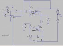
Might want to place a small gate stopper resistor in series right at the gate lead of your IRFP240 to prevent oscillation.
Hy.
For the resistor what value do you think i CAN place. Prevention is better than cure. 😡
cards have already been tested. and they work very well. no oscillations. I think.
Fred.
Hi Fred - welcome to the forum !!!!
You come from a cool island I've never been to, fantastic to see somebody on the forum from exotic locations 😎
Please tell us more about your project - circuit diagram, sound, what speakers do you use with it etc. ?
Thanks.
My project.
I start from zero. the goal is to reconstruct me a system open baffle multi amplified 3-way driven by class A amp.
For the speakers, i use actually my diy ob with electrovoice parts and a
high band range speaker. It´s not finish but the sound in very good for me.🙄
I would like to add in the future two eminence alpha 15. 😀
Sorry for my english.

Fred.
Member
Joined 2009
Paid Member
That's quite an ambitious project - and a lot of fun. Don't forget to consider dc speaker protection (a module from eBay maybe).
The power supply is also very important, do you have any issues with mains hum in the sound ?
The power supply is also very important, do you have any issues with mains hum in the sound ?
Good Work there, Fred.
One thing … While having the MOSFETs connected the way you do is fine, my own inclination would be to experiment with having the output tied back to the inverting input, to close the gain loop from source all the way to the tail. yes, as others will likely chime in quickly, there "are things to consider". But just about all distortion that might come from the MOSFET tail could be reduced to negligible levels.
also - It is kind of late in the design to suggest this, but having the big capacitors above your heat sinks is asking to cook them big-time. Not wise. It would be better to position them just the opposite. Move the heat sink to the top, and put the electrolytics on the bottom.
8 Watts only? I think you're going to get closer to 20 watts.
But what do I know.
GoatGuy
That's quite an ambitious project - and a lot of fun. Don't forget to consider dc speaker protection (a module from eBay maybe).
The power supply is also very important, do you have any issues with mains hum in the sound ?
For Dc speaker protection i use a upc1237.
Datasheet here.
http://www.promelec.ru/pdf/upc1237ha.pdf
An externally hosted image should be here but it was not working when we last tested it.
For the power supply two pi filter. 4700uF->0.22ohms->22000uF->2.2mH->22000uF.
I Will post the schematic todays.🙄
Good Work there, Fred.
One thing … While having the MOSFETs connected the way you do is fine, my own inclination would be to experiment with having the output tied back to the inverting input, to close the gain loop from source all the way to the tail. yes, as others will likely chime in quickly, there "are things to consider". But just about all distortion that might come from the MOSFET tail could be reduced to negligible levels.
also - It is kind of late in the design to suggest this, but having the big capacitors above your heat sinks is asking to cook them big-time. Not wise. It would be better to position them just the opposite. Move the heat sink to the top, and put the electrolytics on the bottom.
8 Watts only? I think you're going to get closer to 20 watts.
But what do I know.
GoatGuy
certainly. but I wanted to make it simple amp. Open loop and single end mos.

The power is limited by the constant current generator. It delivers about 1.5A (Max). So with a 8ohms speakers, the amp Will be around 8W only rms. 😕
The mosfets dissipates 30W in static. the temperature should not rise too. I think. I also install computer ventilators to cool it. 😕
What do you think?
Fred.
Hy there.
Today i start to wire the blocks.
Power supply.
The amp.
Schematics
Speakers protection. Upc1237

Soft start

Fred.
Today i start to wire the blocks.
Power supply.
An externally hosted image should be here but it was not working when we last tested it.
The amp.
An externally hosted image should be here but it was not working when we last tested it.
Schematics
Speakers protection. Upc1237
Soft start
Fred.
Last edited:
Fans dont belong in amplifiers.
Correct. I agree with you. I Will test all Without fans but if the amp is to hot i must use them.

Last edited:
Member
Joined 2009
Paid Member
For the power supply two pi filter. 4700uF->0.22ohms->22000uF->2.2mH->22000uF.
Looks like a good approach to me - the real test will be if you can hear hum or not as SE no-feedback design is the most susceptible. I don't have enough experience to say if you have enough power filters there. The choke is a good idea, will help cut out higher frequency noise (at least up to the limit where the self-winding capacitance of the choke shunts the inductor).
Fans dont belong in amplifiers.
Fans have been used in some famous amplifiers such as Krell KSA 50 without problem.
Last edited:
the temperature should not rise too.
Your heatsinks are identical to Fischer SK56.
300mm X 40mm, 30 ribs.
If their height is as what they appear to be on the pictures, you'll have a temperature problem, and you'll cook the electrolytic cans.
Are you planning to use them with the airconditioning on ?
Thanks all.
😀
My heat sinks are 300mm x 70mm 0.5°/W. For the test. Finally i Will use a 300mm x 150mm. But do you think That 30W dissipate is critical?
For the fans i Will use this. Supply by 8V. It Will be silent.
Fred.
Your heatsinks are identical to Fischer SK56.
300mm X 40mm, 30 ribs.
If their height is as what they appear to be on the pictures, you'll have a temperature problem, and you'll cook the electrolytic cans.
Are you planning to use them with the airconditioning on ?
😀
My heat sinks are 300mm x 70mm 0.5°/W. For the test. Finally i Will use a 300mm x 150mm. But do you think That 30W dissipate is critical?
For the fans i Will use this. Supply by 8V. It Will be silent.
An externally hosted image should be here but it was not working when we last tested it.
Fred.
Last edited:
- Status
- Not open for further replies.
- Home
- Amplifiers
- Solid State
- Class A 8W