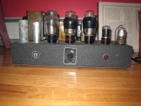
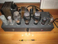
I came across this amp when my school was clearing a science lab. The badge says Clarion Sound System-Transformer Corporation of America. Bottom plate has schematic and adds that this is a Oscillator Amplifier. It uses two 6L6G tubes and a single 5U4Q other tubes are: 6SC7 & 6J7. The power transformer is huge as are the other two.Taps are : G-0-2-4-8-16 Oddly, I don't know where the inputs are! As you may have gathered, I know very little about these things other than how to operate my Dynaco St-70. If anyone has any information on this amp I would greatly appreciate any info. Photos to follow.
Regards,
Jason
Regards,
Jason

Being an "Oscillator-Amplifier", I would think it has no inputs. Oscillator-Amplifier implies an (audio) signal source (the oscillator) driving a power amplifier. I see no frequency control, so it may be fixed frequency.
I have solid state lab gear of similar function. I use one to power the motor in my Garrard 301 turntable. Tweaking the frequency of the motor's power supply (the Oscillator-Amplifier) allows the speed to be set as one wishes. A lot of juke boxes use an oscillator-amplifier to change speed from 33.3 to 45 RPM without having to implement a bunch of additional mechanical devices in an already mechanically complex system.
My 301 runs fast if I power it from the standard 60 cycle wall outlet inasmuch as I've removed the magnetic shunt speed control of the original design. I did so to lower the rumble.
In the design of the 301 speed adjustment is achieved by running the platter a bit faster 33.3 RPM then slowing it down with an adjustable magnetic brake. Much like going 25 MPH in your car by depressing the gas pedal to a point where the car goes 30 MPH, then using your other foot to press on the brakes to slow the car back down to 25 MPH. A lot of extra vibration (rumble) is produced.
Sorry, most of the above is topic-drift, but it may give you some ideas on an application for it.
I'm sure you could do some simple modifications to it to use it as a conventional power amp. You would just need to disable the oscillator portion (which may be as simple as pulling a tube) and then figure out where to inject the audio input signal. The top cap on that one tube (6J7 ? I can't see the pics as I type this) would be a good place to start (as an input point).
Re:Clarion Oscillator Amp.
Dr. Rick.
Thanks for your reply. I was hoping to use this perhaps as a mono sub amp
for high efficiency drivers. I will more than likely surrender it to more capable hands. It seems that a variac would accomplish the same regarding the control of motors etc.. The only application I found on the net was something called a Master Oscillator Power Amplifier (MOPA) that is used to have some effect on Lasers. Anyway, Thanks again.
Jason
NYC
Being an "Oscillator-Amplifier", I would think it has no inputs. Oscillator-Amplifier implies an (audio) signal source (the oscillator) driving a power amplifier. I see no frequency control, so it may be fixed frequency.
I have solid state lab gear of similar function. I use one to power the motor in my Garrard 301 turntable. Tweaking the frequency of the motor's power supply (the Oscillator-Amplifier) allows the speed to be set as one wishes. A lot of juke boxes use an oscillator-amplifier to change speed from 33.3 to 45 RPM without having to implement a bunch of additional mechanical devices in an already mechanically complex system.
My 301 runs fast if I power it from the standard 60 cycle wall outlet inasmuch as I've removed the magnetic shunt speed control of the original design. I did so to lower the rumble.
In the design of the 301 speed adjustment is achieved by running the platter a bit faster 33.3 RPM then slowing it down with an adjustable magnetic brake. Much like going 25 MPH in your car by depressing the gas pedal to a point where the car goes 30 MPH, then using your other foot to press on the brakes to slow the car back down to 25 MPH. A lot of extra vibration (rumble) is produced.
Sorry, most of the above is topic-drift, but it may give you some ideas on an application for it.
I'm sure you could do some simple modifications to it to use it as a conventional power amp. You would just need to disable the oscillator portion (which may be as simple as pulling a tube) and then figure out where to inject the audio input signal. The top cap on that one tube (6J7 ? I can't see the pics as I type this) would be a good place to start (as an input point).
Well if it is an oscillator and power amp then just take the oscillator part out and message the power amp for your application. Looks like it has some decent iron.
Mashafer:
I imagine that given the 1/4 inch of dust I removed from the top the amp that this had not been used in decades. That would suggest that the Caps and other parts may need replacing. I still have a 60hz hum in a Dynaco Pas 2 that I can't figure out. Restoring this beast is beyond my depth. Thanks for the words of encouragement.
I imagine that given the 1/4 inch of dust I removed from the top the amp that this had not been used in decades. That would suggest that the Caps and other parts may need replacing. I still have a 60hz hum in a Dynaco Pas 2 that I can't figure out. Restoring this beast is beyond my depth. Thanks for the words of encouragement.
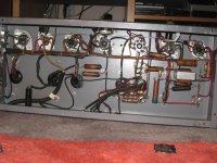
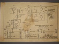
You said that the bottom plate had a schematic. Why don't you post a picture of the schematic, and we can figure out what it is for sure. My guess is that it is what DrRick said, but it might make a good bass amp.
Just noticed that is there is a caution that states that the amp should be used from 50-60 cycles only. This would suggest very limited audio use or am I mixing up my terminology. Maybe a
subwoofer at best?
subwoofer at best?
50 or 60 cycles is the frequency of the AC coming out of the wall, so it's fine running anywhere the line freq. is 50 or 60 Hz. which is everywhere. From the schematic it looks like a normal PP amp after C3. If you where to disconnect C2 and L2 and rearrange a few parts on VT1 you'd have an audio amplifier.
Craig
Craig
The picture of the bottom of the amp shows a very clean and easy to work on design. It also reveals several wax coated paper caps and very old resistors. These and the electrolytics all need to be replaced before any long term reliability could be assured. As suggested minor rewiring of the input section and removal of the oscillator inductance would make this into an amplifier. Is the output transformer capable of handling the frequencies needed for subwoofer duty? That would depend on the power level.
It looks like a good candidate for making a guitar amp though.
It looks like a good candidate for making a guitar amp though.
A little bit of change is needed around the 1'st tube to turn it into an amp and check how well it performs. I expect it may be good for a solo guitar!
By the way, nice 1930'th tubes! If they are working, their place is in a museum! I have one 807 made by RCA in 1939.
By the way, nice 1930'th tubes! If they are working, their place is in a museum! I have one 807 made by RCA in 1939.
Thanks everyone for your help. If it is simply a matter of replacing old caps resistors and addressing the elements you mentioned above (c2,L2&VT) I may make this my first shot at rebuilding an amp. I guess the there is the question too of finding these tubes if the ones I have don't work!
Thanks again,
Thanks again,
I guess the there is the question too of finding these tubes if the ones I have don't work!
The 6L6G's are somewhat a collectors item although I have found them in the dollar bins at hamfests occasionally. This is not a problem because you can substitute any of the later 6L6 variants including the 6L6GC which is still being made. Ditto the 5U4G. The other two are often found in old radios and still available from anyone who sells tubes for this market.
Thanks, that's good to know that the tubes are still out there.
I'll update if I take this project on.
-Jason
I'll update if I take this project on.
-Jason
Jason,
It looks like it would be real easy to convert that to a tube amp. Input would be at R6.
Sal
It looks like it would be real easy to convert that to a tube amp. Input would be at R6.
Sal
- Status
- Not open for further replies.
- Home
- Amplifiers
- Tubes / Valves
- Clarion 6L6G Oscillator Amp.