Hello Everyone,
I'm a student at Cal Poly that's trying to learn about amplifier design and repair. I've been teaching myself very slowly, and i've run into a problem.
I took on a project repairing a Citation twelve deluxe. Here is what I'm currently seeing:
On pins 10 and 12, I'm seeing a voltage of -0.043 and -0.023, respectively.
On pins 17 and 19, I'm seeing a voltage of -0.048 and -0.068, respectively.
My supply voltages are +/- 37.5V, and every other pin is within a normal range except these. This makes me believe the outputs are either being biased incorrectly or are damaged.
Is this the correct assumption? Thank you for your time
Schematic would be helpful.
You might want to check this thread.
http://www.diyaudio.com/forums/solid-state/62400-help-needed-repairing-hk-citation-12-a.html
You might want to check this thread.
http://www.diyaudio.com/forums/solid-state/62400-help-needed-repairing-hk-citation-12-a.html
Last edited:
thanks for the reply, RJM1.
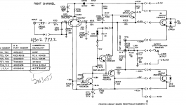
here's a copy of the schematic.
that thread recommends that I just replace most of the transistors. is that the direction i should be headed? will an aging transistor cause a drift like that?
here's a copy of the schematic.
that thread recommends that I just replace most of the transistors. is that the direction i should be headed? will an aging transistor cause a drift like that?
in case uploads are getting screened out, here's a link to the manual.
Citation Twelve Sm[1]
I'd like the manual (my 1st power amp was a Citation 12 i built from a kit), but your link requires login to facebook which makes it useless to the 50-some% of people who won't have anything to do with facebook. Can you provide an alternate link?
dave
I believe you are going after the wrong thing. In between those voltages you are measuring is the output. It simply means the output offset is -.033V (-33mV) in one channel and -.058V (-58mV) in the other. Both channels have a total difference of 20 mV, which means idle current in either channel is 20mV divided by .54 ohms (two .27 ohm resistors) or 37 mA which is probably what close to what HK recomended.
Output offset is pretty much a function of the input pair of transistors and their operating points. Ideally it should be zero, but these numbers are fairly typical of what you find.
Output offset is pretty much a function of the input pair of transistors and their operating points. Ideally it should be zero, but these numbers are fairly typical of what you find.
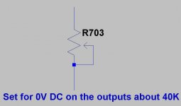
If you replace the input resistor R703 (33K) with a 50K pot as a DC level adjustment control you should have enough range to zero the outputs. If you increase the value of R703 the DC on the output will go more positive. Since both of your channels have a negative offset -30mv and -50mv the correct value for R703 to zero the DC offset on the output should be somewhere around 40K. As Sregor pointed out your bias values are probably about right.
Attachments
Last edited:
In the orgiinal modification article by Pass, there is a schematic which indicates that R705 was changed to 12k in later versions. This would help balance the currents in the input pair. It also would reduce the negative offset. It also mentioned that the input pair was changed to a matched pair of 2n5087 as the original part was no longer available.
Link to citation 12 mods http://www.passdiy.com/pdf/citation.pdf
Link to citation 12 mods http://www.passdiy.com/pdf/citation.pdf
Last edited:
- Status
- Not open for further replies.
- Home
- Amplifiers
- Solid State
- Citation Twelve Deluxe Repair