Trying to understand
there is an old circuit that i'm interested to replicate, that supposedly exhibit a sound imprint that is whose I'm looking for.
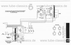
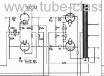
The push pull of 6BQ5 is driven by a simple commom K amplifier whose output feeds a second common K , but trough a voltage divider to achieve phase splitting an unity gain.
I understand this is called a "paraphase splitter"
The signal tube is the 6EU7, a high mu double triode, similar to the well known 12AX7.
Nevertheless, I'm curious about some apparently weird circuit solutions:
different coupling caps (0.0068 vs 0.047 uf) to the upper and the lower tube of the PP
Same thing for RL 470K vs 220K
Finally, while RA is the same for the two 6EU7 halves, Rk isn't : 1500+390 vs 5600 ohms.
I suppose that to replicate the circuit sonics using a different set of parts, it's better to understand by first , the reasons behind this kind of asimetry.
Any thoughs?😕
there is an old circuit that i'm interested to replicate, that supposedly exhibit a sound imprint that is whose I'm looking for.
The push pull of 6BQ5 is driven by a simple commom K amplifier whose output feeds a second common K , but trough a voltage divider to achieve phase splitting an unity gain.
I understand this is called a "paraphase splitter"
The signal tube is the 6EU7, a high mu double triode, similar to the well known 12AX7.
Nevertheless, I'm curious about some apparently weird circuit solutions:
different coupling caps (0.0068 vs 0.047 uf) to the upper and the lower tube of the PP
Same thing for RL 470K vs 220K
Finally, while RA is the same for the two 6EU7 halves, Rk isn't : 1500+390 vs 5600 ohms.
I suppose that to replicate the circuit sonics using a different set of parts, it's better to understand by first , the reasons behind this kind of asimetry.
Any thoughs?😕
Sounds like a Magnavox amp 🙂 The paraphase circuit is prone to a low-frequency oscillation ("motorboating") if you DON'T "stagger" the cutoff frequencies of the two R-C circuits.
Technically it's known it as a paraphase inverter.I understand this is called a "paraphase splitter"
http://www.audioxpress.com/resource/audioclass/ga200ac.pdf
I have build that amp. There are better paraphase splitter circuits.
If you're interested I can post a better one.
If you're interested I can post a better one.
Ok, so.. it is to avoid oscilation issues and not to tailor the distortion pattern to make it "nice".
🙂 Yes, it is a Magnavox.
🙂 Yes, it is a Magnavox.
Last edited:
Stalker, I'm interested.
I'd like to know your opinion on the amp you have built, too..
I'd like to know your opinion on the amp you have built, too..
Last edited:
Stalker, I'm interested.
Well, first of all, better is a subjective word. HollowState posted a circuit I have tried too. Sounds good, "better" than the Magnavox but the "best" one is this self balancing floating paraphase:
The Valve Wizard
Leben uses that one too. Smart guys, the Japanese have good ears:
6moons audio reviews: Leben CS-300X
I'd like to know your opinion on the amp you have built, too..
Magnavox clone? Bah... nothing to write home about.
🙂Bah... nothing to write home about.
Well, I'll try the one and the other, and then, decide
Thanks for the valuable info
Well, I'll try the one and the other, and then, decide
Wise man.
Thanks for the valuable info
You're welcome.
Nice! thanks.
I'm not certainly an expert, but I think the Magnavox style is opposite to modern audiophile design goals. It is a hign gain, narrow open loop passband, that is flattened and extended by using heavy global NFB.
So, pure pentode mode and high gain input stage, big RA resistors and low current operating point.
It is correct?
PD and not to forget , a single Rk resistor shared by the four output tubes
Last edited:
I'm not certainly an expert, but I think the Magnavox style is opposite to modern audiophile design goals.
It's not an LTP with a current source so I guess you're right. 🙂
So, pure pentode mode and high gain input stage
Gain is low, I think it was 6 or 9. Anyway the high gain tube and GNFB is pretty common in pentode PP amps.
PD and not to forget , a single Rk resistor shared by the four output tubes
Yeah, weird stereo effect.
One more thing, I would suggest trying a 5K pot in place of the feedback resistor. You need to know how much feedback is needed. Some speakers need more, others less. You'll learn a lot, fun to make your tube amp sound like transistors just by rotating a knob.
Bypass cap depends of your OTs so the value is orientative.
Bypass cap depends of your OTs so the value is orientative.
Attachments
Yeah, I was trying with the pot trick before, to determine the amount of FB in a self splitting experimental circuit. You definitely notice when the amount of FB become too much, it start to scream like a banshee 🙂
- Status
- Not open for further replies.
- Home
- Amplifiers
- Tubes / Valves
- Circuit weirdness?