Hello,
I have late 80s equalizer that I would like to modify for PA use.
I would like to keep the slider pots, they are in good condition, not scratchy or anythink and build new circuitboard for it.
It`s a 2(stereo) x 5band, pots are 100kOhm.
And I would also need gain control to match consumer line level to professional line level.
I already made circuit for gain control, lpf and bass boost thanks to user "Mooly", this is the design of gain control:

However I will try to modify it for +-15v supply, so it will be able to get higher gain before clipping.
I`m thinking of putting this circuit before the EQ.
Than I also have low pass filter and bass boost that I will use in this project (for now I think that this will not be EQed or that I will add a switch to select if it will be or not).
So the main thing is that I would need circuit for 5band EQ, with 100k pots, supplied by +-15v or only +15v. I would like to made it with NE5532 or TL072 IC`s (I like what I hear with my NE5532 and TL072 based circuits and I can get them near me).
Faceplate have labeled frequencies 60hz, 250hz, 1khm, 4khz and 16khz, but it`s not important to me to keep this settings...
I tried to upload pictures of eq in case anyone would like to see, but for some reason it doesn`t want to upload, will upload it later.
Thank you for your help
I have late 80s equalizer that I would like to modify for PA use.
I would like to keep the slider pots, they are in good condition, not scratchy or anythink and build new circuitboard for it.
It`s a 2(stereo) x 5band, pots are 100kOhm.
And I would also need gain control to match consumer line level to professional line level.
I already made circuit for gain control, lpf and bass boost thanks to user "Mooly", this is the design of gain control:
However I will try to modify it for +-15v supply, so it will be able to get higher gain before clipping.
I`m thinking of putting this circuit before the EQ.
Than I also have low pass filter and bass boost that I will use in this project (for now I think that this will not be EQed or that I will add a switch to select if it will be or not).
So the main thing is that I would need circuit for 5band EQ, with 100k pots, supplied by +-15v or only +15v. I would like to made it with NE5532 or TL072 IC`s (I like what I hear with my NE5532 and TL072 based circuits and I can get them near me).
Faceplate have labeled frequencies 60hz, 250hz, 1khm, 4khz and 16khz, but it`s not important to me to keep this settings...
I tried to upload pictures of eq in case anyone would like to see, but for some reason it doesn`t want to upload, will upload it later.
Thank you for your help
As an afterthought I would rather use +-12v, because I will sometimes power the system by generator, and I would like to add voltage regulators and insure stable +-12v.
Remove Rbias1. Link out Rbias 2. Remove the -ve pin of the IC and connect it to new -ve rail. Ov point is now the link at Rbias2 point. Decouple the +ve pin to 0v and decouple the -ve pin to 0v using 10uF electrolytics. This will work with + - 9v upwards to the maximum voltage of the IC.
Remove Rbias1. Link out Rbias 2. Remove the -ve pin of the IC and connect it to new -ve rail. Ov point is now the link at Rbias2 point. Decouple the +ve pin to 0v and decouple the -ve pin to 0v using 10uF electrolytics. This will work with + - 9v upwards to the maximum voltage of the IC.
Thank you for this
Remove Rbias1. Link out Rbias 2. Remove the -ve pin of the IC and connect it to new -ve rail. Ov point is now the link at Rbias2 point. Decouple the +ve pin to 0v and decouple the -ve pin to 0v using 10uF electrolytics. This will work with + - 9v upwards to the maximum voltage of the IC.
I draw schematic, if you could take a look at it and let me know if I did it as you meant.
Specificly I`m unsure about Rbias2 resistor.
Here is the original that I had to redraw:

Here is the modified version:

Thank you for you help.
Ok, so I have found something that may be suitable for me. It`s a 5band, all pots are 100k, and frequencies can be easily changed with different capacitor values...
But question is: Will I get good quality sound from LA3600 IC?

But question is: Will I get good quality sound from LA3600 IC?
I had also found BA3812L, I guess that this one is better than LA3600?
It is also 5band and uses 100k pots 🙂
Datasheet states that this IC is ideal for Hi-fi?

It is also 5band and uses 100k pots 🙂
Datasheet states that this IC is ideal for Hi-fi?
And this...
This circuit is designed for 4558, but I would use NE5532 or TL072... Would this be better than LA3600? I can`t get BA3812L ic, I called the store...

This circuit is designed for 4558, but I would use NE5532 or TL072... Would this be better than LA3600? I can`t get BA3812L ic, I called the store...
Hi, if it's for PA use I wouldn't be too concerned about Hi-Fi quality, any of those will do the job. Equalisers
Hello,Hi, if it's for PA use I wouldn't be too concerned about Hi-Fi quality, any of those will do the job. Equalisers
I would like it to sound as best as I can... I would use LA3600, but i don`t know, when I saw it`s application list, first thing that I tought of is that useless EQs in walkmans...
Do you have any experience with LA3600? I realy don`t know what to expect from it? I`m satisfied with NE5532 and TL072 quality...
I have a realy nice, dynamic sounding amp, later I will buy some good speakers, so I don`t want so sacrifice quality
Thank you for the link.
I will try to find some information, it`s Yugoslavian RIZ from 1988, there is one transistor for one pot... Will dig a little and let you know...What is the equaliser you have, do you have a schematic or know it's topology?
I will try to find some information, it`s Yugoslavian RIZ from 1988, there is one transistor for one pot... Will dig a little and let you know...
There is no schematic on the internet. The best I can do is the picture of it's pcb.
Attachments
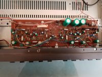
I readed thru the website and I can`t find out if this is good or bad. The EQ doesn`t sound right to me... Maybee replacing capacitors and resistors would sort this out. But there are alot them, so I think that building something new with 2 ICs or more would be better option, plus it would make the circuit more compact.It probably uses gyrators built around emitter followers. Example in section 7 Gyrator Filters
It's not easy to decide what's best. With a graphic with only a few bands you can almost guarantee they aren't going to be where you want or need them.
It's not easy to decide what's best. With a graphic with only a few bands you can almost guarantee they aren't going to be where you want or need them.
I agree.
I would at least go 10 band.
32 64 125 250 500 1k 2k 4k 8k 16k Hz.
More is better of course.
Last edited:
The Cello Palette used 6 cleverly spaced bands but it was a very special beast
Yes, clever design on that one.
For 6-band as good as it gets.
Cello Palette Preamplifier Measurements | Stereophile.com
So this might be the problem (using only 5 bands)... you see I don`t have much experience with EQs.
Did you ever need to EQ left ch different than right ch? Assuming that both speakers are the same and are in the same room?
I`m asking this because I could istead of making 2x5band make 1x10band EQ, still stereo, but both channels would be controlled by the same pots. Then I would need to find IC that has direct input pin, instead of input being linked to the pots, if it even exist...
Last edited:
- Status
- Not open for further replies.
- Home
- Source & Line
- Analog Line Level
- Circuit for 5band EQ...