It can be repaired and look pretty too:
http://www.circuittechctr.com/
It just won't be cheap. You can do it ot have it professionally done.
See an actual repair:
http://www.circuitmedic.com/guides/3-0.shtml
http://www.circuittechctr.com/
It just won't be cheap. You can do it ot have it professionally done.
See an actual repair:
http://www.circuitmedic.com/guides/3-0.shtml
Glen
Do you have any idea what the SCR part number is.A service manual would be handy.Because all of that carbonized area will need to be removed .Especially around all copper traces and solder pads(carbon is a fairly good conductor) This will require removing part of the pcb and some of the copper traces.The cut traces will need to be jumpered with insulated wire. Take some real detailed photos and make some notes as to where traces need to go before removing any carbon.The tricky part will be finding a new home for SCR..............feel like bailing yet?LOL 😉
Dave
I was going to reccomend the circuit medic stuff. First all the carred aread will need to be completly scraped away. then using some circuit medic epoxy and coloring agents if you wish, you will have to fill in the whole area. put some polymide or kapton tape on one side and fill the are with epoxy from the other. if you are carefull you can get it pretty level.
Once the epoxy had hardened for several days, you can then sand it down flat and drill new holes. then use the circuit medic trace repair kits and plated through hole repair kits and you make that board look like new.
All of that is very expensive and a lot of work however.
You could try off the shelf epoxy and wire. or if your local electronics shop has some circuit trace tape, that would probably turn out ok.
I recently did some repair of lifted traces from a board using a very similar method. I had a pad that came loose that had 3 traces connected to it, 2 of the 3 traces broke. I cleaned the area and used some epoxy very carefully to glue the pads and traces back down making sure to clean any excess off. I use some small felt pads on a spring clamp to hold the traces and pads down one at a time. after the epoxy had set about 1-2 hours, i then removed the clamp carefully and cleaned any fibers from the felt that stuck to the epoxy off. I then let the board air dry.
Once the epoxy had fully cured. then i scraped off the solder mask and cut some narrow strips of some copper PCB repair sheets. I tined the PCB traces and tinned the copper strips, then soldered the strips down over the traces and across the pad. then i carefully cut the new trace strips to size and use the supplied tool to cut a hole through the traces. i slipped ina plated through hole rivet and swedged it on the other side. the applied just a little bit of solder to hole the rivit in place, but not enough to get in the hole.
I then applied just a dab more epoxy to the tops of the new traces to help hold them down and dissapate a little bit of heat when i resoldered the device back to that hole.
All in all the rapir came out excellent, and if i could have colored the epoxy green, at the end it would have taken a keen eye to spot the repair!
Zc
Update
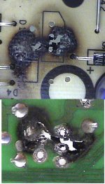
I decided to do a filler repair on the hole that the SCR
burnt through the board. I spotted some stuff that was
very close to being the same color as the pc board. The
only problem was that the maximum temperature rating
was 200 degrees Fahrenheit. That was just too low for my taste.
So I spotted something that rated at 600. The name of that something is (don’t laugh) JB Weld (cold weld compound). I was concerned whether or not it would conduct electricity but it doesn’t and the manufacturer claims this as well. It bonded nicely to the surrounding circuit board area. I made sure I cut out the damaged carbonized area first. Once it completely hardened I ground off the excess. The dark edge was surface discoloration and was pretty easily removed afterwards.

I then drilled the holes for the SCR and remounted the surrounding components. Since there were various areas on the board that were already screened in black I decided to black out the area of the repair as a rectangle to help cover the repaired surface.

Here’s the bottom side,
Its not real pretty but quite solid and functional.

The end result.

I decided to do a filler repair on the hole that the SCR
burnt through the board. I spotted some stuff that was
very close to being the same color as the pc board. The
only problem was that the maximum temperature rating
was 200 degrees Fahrenheit. That was just too low for my taste.
So I spotted something that rated at 600. The name of that something is (don’t laugh) JB Weld (cold weld compound). I was concerned whether or not it would conduct electricity but it doesn’t and the manufacturer claims this as well. It bonded nicely to the surrounding circuit board area. I made sure I cut out the damaged carbonized area first. Once it completely hardened I ground off the excess. The dark edge was surface discoloration and was pretty easily removed afterwards.
I then drilled the holes for the SCR and remounted the surrounding components. Since there were various areas on the board that were already screened in black I decided to black out the area of the repair as a rectangle to help cover the repaired surface.
Here’s the bottom side,
Its not real pretty but quite solid and functional.
The end result.
Looks like job completed to me . Good work probably saved $100!!
A new control is $148.00. I wasn’t about to scrap the old one over
a power supply fault.
What time is Dinner? LOL
Whenever I pull myself away from the bench or computer. 🙂
- Status
- Not open for further replies.
- Home
- General Interest
- Everything Else
- Circuit Board Blowout