Hey all.
Are there any rules of thumb for choosing filter types for certain drivers? Like how do I know when to use a Butterworth, Linkwitz Riley, Bessel... etc.
Do the small Thiel parameters give hints on what to use?
Sorry if this has been asked, I couldn't find the answer I was looking for.
Thanks in advance! 😕
First order filters really don't work well with regular tweeters, although I'm sure they sound lively. In practise you always invariably use a second order on the bass. The variable is how quickly you roll it off and how big the coil is for bafflestep correction if you need it. There is a relation between Qts and what box you use. Qts= 0.3-0.4 says bass reflex. 0.5 means closed box. Vas then tells you roughly how big the box is. There is also a relationship between voicecoil inductance Le and the size of filter components you need.
Awkward resonant drivers like metal cones need quite steep rolloff to avoid resonances breaking through into the tweeter range, and can sound hard and unmusical.
Tweeters have similar issues. Well behaved ferrofluid domes like the visaton G 20 SC are easy enough on second order.
Visaton - Lautsprecher und Zubehör, Loudspeakers and Accessories
Badly behaved ones like the visaton TW 70 need a third order to get good slopes.
Visaton - Lautsprecher und Zubehör, Loudspeakers and Accessories
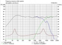
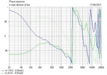
Oddly enough, some combinations of woofer and tweeter are particularly tidy. 6.5" paper woofer and dome tweeter is a nice one to work with on second order. 5" woofer and dome tweeter works very well with a third order on the tweeter because it has good phase alignment at crossover. I'll stop there, having left you a goodish performing example to ponder. Notice the 6dB rolloff at crossover, which says phase is OK. Also that the slopes are similar.
Awkward resonant drivers like metal cones need quite steep rolloff to avoid resonances breaking through into the tweeter range, and can sound hard and unmusical.
Tweeters have similar issues. Well behaved ferrofluid domes like the visaton G 20 SC are easy enough on second order.
Visaton - Lautsprecher und Zubehör, Loudspeakers and Accessories
Badly behaved ones like the visaton TW 70 need a third order to get good slopes.
Visaton - Lautsprecher und Zubehör, Loudspeakers and Accessories
Oddly enough, some combinations of woofer and tweeter are particularly tidy. 6.5" paper woofer and dome tweeter is a nice one to work with on second order. 5" woofer and dome tweeter works very well with a third order on the tweeter because it has good phase alignment at crossover. I'll stop there, having left you a goodish performing example to ponder. Notice the 6dB rolloff at crossover, which says phase is OK. Also that the slopes are similar.
Attachments
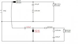
It might be best to say you won't go wrong with a Linkwitz-Riley slope, and fourth-order seems to come up often. The slope you get will be a combination of the driver's natural goings on, and the filter you use so unless you measure things you won't be certain. Not that this on its own will lead to bad sound.
It might be best to say you won't go wrong with a Linkwitz-Riley slope, and fourth-order seems to come up often. The slope you get will be a combination of the driver's natural goings on, and the filter you use so unless you measure things you won't be certain. Not that this on its own will lead to bad sound.
The chebycheb seems to be the most cost-effective.... smaller inductors. But I guess I can just try them all. I was hoping for somthing like. "yeah, a low QTS or QES wants a Bessel configuration yadda yadda"
Thanks!
High Q filters like Butterworth and Chebyshev just give you huge peaks in response. 😀
You have to model this to believe it, but drivers really design their own filters. Linkwitz-Riley electrical is often where it's at. People then notice that the overall response is something like 18dB or 24dB per octave eventually.
All this gets traded off a bit, when you find that gentler smoother slopes sound better.
If it helps, I don't limit myself to a particular slope even across a single crossover. At each frequency within the range I decide which driver I want to be the dominant one and how much overlap I need at that point in the system. I also don't worry too much about filter Q as long as it isn't extreme (and works for the job).
For what it's worth, system7 has found his method often gives good results for a given driver based on driver specs.
For what it's worth, system7 has found his method often gives good results for a given driver based on driver specs.
You have to model this to believe it, but drivers really design their own filters.
I believe it. That is why I am asking 😉
Furthermore, using a Chebyshev filter won't guarantee you a Chebyshev slope. If found that using a Chebyshev slope gave me the end result I needed, that would be more important to me.
Furthermore, using a Chebyshev filter won't guarantee you a Chebyshev slope. If found that using a Chebyshev slope gave me the end result I needed, that would be more important to me.
There's a way to look at this. A tweeter without a filter has broadly a second order butterworth response. Give it an electrical second order butterworth and as we all know, two cascaded 2nd order butterworths give a fourth order Linkwitz-Riley. Job done. 😎
My rule of thumb for woofers in bookshelves is you give it a bafflestep coil equal to the Le inductance. The rolloff capacitor is then Le/ (Re squared) times a fudge factor of 0.666. Naturally this works best with low inductance woofers to get a reasonably high crossover point. I'd then model it to get it just right. Floorstanders and the HIDEOUS bafflestep correction is so laughably WRONG that I won't waste time on it. Er, just my opinion. 😀
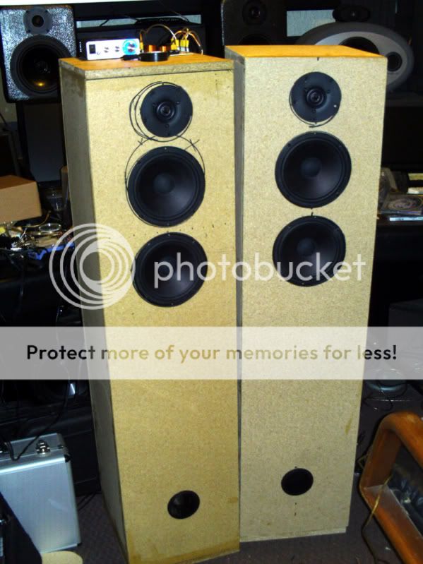
These are floorstanders... 12"x14"x48". They have (2) 6 1/2" woofers and a 1" tweeter.
Unfinished. most likely will get a laminate or a melamine
Unfinished. most likely will get a laminate or a melamine
Ah, floorstanders. Marvellous. 😱
So you're going to parallel the woofers and hope the tweeter can keep up with the loudness. How are you getting on? What are the drivers?
So you're going to parallel the woofers and hope the tweeter can keep up with the loudness. How are you getting on? What are the drivers?
Ah, floorstanders. Marvellous. 😱
So you're going to parallel the woofers and hope the tweeter can keep up with the loudness. How are you getting on? What are the drivers?
Yes, paralleling the drivers to 4ohm. The tweeter is 4ohm so it matches quite well. The amount of bass I'm getting out of these is wonderful.
Cheap drivers... I have them crossed around 2k, 2nd order Bessel atm
Focal 6M115 6-1/2" Midbass Speaker 299-155
Vifa XT25TG30-04 1" Dual Ring Radiator Tweeter 264-1016
That is a nice choice in a tweeter the Vifa XT25. System7 and AllenB are credit to the forum.
Using both Focal 8m118 drivers in parallel does lower the voice coil mh in the equation. I would not expect very much bass due to driver Fs unfortunately.
Using both Focal 8m118 drivers in parallel does lower the voice coil mh in the equation. I would not expect very much bass due to driver Fs unfortunately.
as system7 says, simulation helps a great deal with the choice of filter order. Sometimes chebychev is useful to fill a small hole in response around the crossover point, just as 3rd order is useful to tame a peak at the lower end of the tweeter response when paired to a 2nd order low pass. In reality, i believe filter 'type' is not important since with simulation we mostly end up with a slope which doesnt directly match any type, but is somewhere between. Just like plenty woofers with qts of 0.3 to 0.4 have and will again be used in sealed boxes. Like the LS5/3A i believe. Those use rather alot of baffle step compensation too i believe the full 6db.
Last edited:
In reality, i believe filter 'type' is not important since with simulation...
Yes, the filter you apply is actually the combination of the components and the complex impedance of the speaker, which won't be what you get from standard formulas... but it doesn't stop there. Since the response of the speaker is probably not flat to begin with you need to take the difference into account when you choose the filter in the first place.
It is tough to guess this but possible to do to some degree with trial and error using just a box of components, some clip leads and your ears, but it will be a long process. Even with experience, you can minimise your steps by pushing your errors in the 'right' direction, but there will still be head scratching and perfection may be too difficult to achieve.
Using a single measurement on your listening axis will greatly simplify the process. Measuring the drivers together and separately, then looking at those three plots together allows you to estimate whether you have the drivers well in phase. Not doing so will change the ratio of room power to direct sound, among other things.
The problem with this is that a flat on axis response does not indicate that you've necessarily done the crossover right. This is why I believe that you should either do a crossover properly, or involve your ears. Your ears will hear more than on axis measurements can tell you, but even your ears have their limits.
I have a Vidsonix passive virtual crossover box and (2) digital 3way crossovers for dialing in the crossover points. I do take a much as I can into consideration. I trust my ears completely.
There is really too much reliance on "name dropping" with filters/crossovers. Bessel, Butterworth, Chebyshev... these (all-pole filters) are mostly just points along a continuum in which the filter Q, and the placement of filter resonance frequency with respect to the filter corner frequency, vary.
You can state one or two or three generalizations for sure:
Gentler slopes (lower Q or lower order filters) have better time domain response (e.g. better transient response, less ringing) and less group delay.
Higher Q and higher order filters have better "selectivity", meaning they have a steeper slope and thus a smaller transition region between passband and stopband, but also have higher group delay, often peaking near the crossover point.
That's it!
So pick your poison, so to speak. You have to keep in mind the penalties that you will suffer when you go too far in one direction or the other (filter order or Q too low or too high). As someone mentioned, first order filters are not typically used because they don't provide enough attenuation out of band. Higher order (e.g. above 6th order) filters approach the point where the group delay is getting so severe that it is audible, depending on the type of filter used (e.g. how high is the Q of each stage in the filter).
When designing loudspeakers, you have to take in to account the phase response of the filters and the drivers. These are both changing as a function of frequency, and this is a very important point, because when the phase approaches 180 degrees (out of phase, or anything over 120 degrees) there will be cancellation and dip in the frequency response. I use sophisticated modeling software to account for all phase responses when I design a crossover. I care less about the order or type of filter, and more about summing in phase and sufficient out-of-band (e.g. stopband) attenuation. This is probably one of the most overlooked issues in speaker design by the "average" dabbler in DIY loudspeakers, and it doesn't matter whether you use passive or active crossovers.
You can cook up whatever crossover filters you would like once you see that the well-known "named" filters are just examples of the broad spectrum of what is possible.
-Charlie
Last edited:
Great post Charlie....You can cook up whatever crossover filters you would like once you see that the well-known "named" filters are just examples of the broad spectrum of what is possible.
Does anyone know of a 'cheat sheet' on the web somewhere that lists all those names on some sort of graph all in one place?
I would think that would be kind of handy.
Great post Charlie.
Does anyone know of a 'cheat sheet' on the web somewhere that lists all those names on some sort of graph all in one place?
I would think that would be kind of handy.
Not a cheat sheet, but a good resource with lots of relevant information is:
http://www.analog.com/library/analogDialogue/archives/43-09/EDCh 8 filter.pdf
Sections 8.1 to 8.4 are informative in general, especially starting at page 8.21. There are lots of plots of the filter types given starting on page 8.31.
-Charlie
- Status
- Not open for further replies.
- Home
- Loudspeakers
- Multi-Way
- Choosing filter type