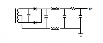
I took a look around on here but couldn't find anything, so I thought I would ask. I found this schematic for a power supply and it had a choke in the ground attached between the first and second cap in the power supply (as well as one on the B+).
Is there any reason to do this? Pic attached
Is there any reason to do this? Pic attached
Attachments
If they have a common core. You will have a common mode noise filter.
Sent from my Nexus 6P using Tapatalk
Sent from my Nexus 6P using Tapatalk
If they have a common core. You will have a common mode noise filter.
Sent from my Nexus 6P using Tapatalk
No common core on these. They are two separate chokes.
It means the choke has to stand less voltage. Commonly used in higher voltage supplies. Sometimes used to obtain a negative bias supply.
It means the choke has to stand less voltage. Commonly used in higher voltage supplies. Sometimes used to obtain a negative bias supply.
I wonder why it was used in this design then. The secondary wasn't very high voltage (300-0-300). It also doesn't use any negative bias supply (I can't post the full schematic)
Does it offer any noise advantage?
Last edited:
It does help with mains common-mode noise/rectifier diode switching RFI, instead of the transformer (secondary center-tap) coupling all that to audio GND. It depends how the transformer is wound (split bobbin or not).
Last edited:
It does help with mains common-mode noise/rectifier diode switching RFI, instead of the transformer (secondary center-tap) coupling all that to audio GND. It depends how the transformer is wound (split bobbin or not).
This was my assumption when i tried it. Surprising improvement even though i use no sand diodes.
Having a negative line choke forces people to avoid the common mistake of directly grounding the secondary CT.
Lundahl from Sweden have this thing dual windings on one core.
Maybe its better to use it this way than use the windings in series (only on the possitive side)?
Maybe its better to use it this way than use the windings in series (only on the possitive side)?
No common core on these. They are two separate chokes.
The usual coupling of common-mode choke windings on a single core is so that the choke doesn't also impede normal-mode A.C. current flow. Two fully independent chokes as located in your schematic will perform dual service, impeding both normal-mode and common-mode A.C. current.
That sounds pretty good then.The usual coupling of common-mode choke windings on a single core is so that the choke doesn't also impede normal-mode A.C. current flow. Two fully independent chokes as located in your schematic will perform dual service, impeding both normal-mode and common-mode A.C. current.
I have some 10H 50mA (500DCR) chokes at home.
I could try them out doing this for a preamp power supply. Should I try it?
Andrew
That sounds pretty good then.
I have some 10H 50mA (500DCR) chokes at home.
I could try them out doing this for a preamp power supply. Should I try it?
Andrew
An issue could be the 500 ohm DCR of each coil. Together, two chokes will introduce an 1k ohm resistance that may unacceptably drop the D.C. voltage output of the supply. The D.C. output will be reduced by a voltage drop equal to 1k times the D.C. current flow.
Assuming that the D.C. drop is acceptable, make certain the electrolytic supply capacitors following the chokes are sufficiently large, as they would be responsible for setting the A.C. output impedance of your choke fed supply.
At 40mA that I planned to run it, you think 40v would be too much of a drop? I'm also using a 300-0-300 supply, but 40v doesn't sound too bad.An issue could be the 500 ohm DCR of each coil. Together, two chokes will introduce an 1k ohm resistance that may unacceptably drop the D.C. voltage output of the supply. The D.C. output will be reduced by a voltage drop equal to 1k times the D.C. current flow.
Assuming that the D.C. drop is acceptable, make certain the electrolytic supply capacitors following the chokes are sufficiently large, as they would be responsible for setting the A.C. output impedance of your choke fed supply.
I was planning on tube rectification, which would rule out using large capacitors, though.
1k supply impedance doesn't just apply to DC, but also to subsonics. The result can be motorboating, unless the amp has a sufficiently high LF rolloff.
At 40mA that I planned to run it, you think 40v would be too much of a drop? I'm also using a 300-0-300 supply, but 40v doesn't sound too bad.
I presume that 40mA is the expected draw for both channels in total, otherwise, the drop would be 80V. Whether a 40V drop is even too much depends on what D.C. voltage you require at the output of the supply.
I was planning on tube rectification, which would rule out using large capacitors, though.
Not necessarily. If the capacitor before the chokes isn't large, which it doesn't need to be given that your suppy forms a pi-filter, then the peak current draw from the necessarily larger capacitors located after the chokes will be limited by the 1k ohm DCR of the chokes. Designing even an unregulated power supply isn't ncessarily as simple as it might at first seem. 😉
By the way, here's an easy and fun to use little online calculator which assists in designing a choke filtered power supply. It's located at the bottom of the linked page. Don't forget to sum the inductance and DCR values of the two chokes for entry in the calculator, which assumes a single choke. Since your two chokes are in series with each other, they will behave as a single larger choke, so the claculator will still produce correct results if you sum their values.
Hagerman Technology LLC: Design Theory
Hagerman Technology LLC: Design Theory
Last edited:
I presume that 40mA is the expected draw for both channels in total, otherwise, the drop would be 80V. Whether a 40V drop is even too much depends on what D.C. voltage you require at the output of the supply.
That is correct 😉
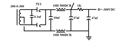
Yep, it sure can be. Does this look well? (see attached. The point after the choke goes to the 2nd channel. each channel pulls 20mA)Not necessarily. If the capacitor before the chokes isn't large, which it doesn't need to be given that your suppy forms a pi-filter, then the peak current draw from the necessarily larger capacitors located after the chokes will be limited by the 1k ohm DCR of the chokes. Designing even an unregulated power supply isn't ncessarily as simple as it might at first seem. 😉
Attachments
That is correct 😉
Yep, it sure can be. Does this look well? (see attached. The point after the choke goes to the 2nd channel. each channel pulls 20mA)
Honestly, I'd have to review the 5Y3 data sheet to say, which I'm feeling too lazy to do at the moment. So long as the peak current draw doesn't exceed the the capablity of the 5Y3, you're probably safe. The peak draw will occur when the caps. are completely discharged, which typically means at the moment of power switch-on. However, the 5Y3 will need to warm up, and so will progressively conduct as it warms up, not conduct immediately the way a silicon rectifier would. Which means the worst case peak current draw at power-on will be reduced.
You could reduce the size of that first capacitor just after the 5Y3 even further. It could also be eliminated altogether, which would remove any doubts due to it's presence. However, I like to use at least a small value cap. in this position to help stabilize the feed to the chokes. Consult the calculator I recommended to design the supply as 2-pole, with only the chokes followed by the output caps.
Last edited:
- Status
- Not open for further replies.
- Home
- Amplifiers
- Power Supplies
- Choke in power supply ground