
C3 is only 100nF, it will have disastrous effects. A more sensible option is to insert the choke between the first pair of C2's and the second pair
to the marked place in the picture?C3 is only 100nF, it will have disastrous effects. A more sensible option is to insert the choke between the first pair of C2's and the second pair
Attachments
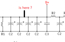
Or to between the first C2 and the other three. Perhaps need to check with PSUD2 (once the PT and choke and operating parameters are measured) to see if there is a better damped outcome. Measuring the parameters and doing a PSUD2 sim is also a sanity check that you are going to use a suitable choke, but what is suitable (and using PSUD2) may require some experience, and not a simple guess.
If the layout of transformer and bridge and first C2 are tight then I'd suggest removing all C1 caps, given UF400x are being used.
If the layout of transformer and bridge and first C2 are tight then I'd suggest removing all C1 caps, given UF400x are being used.
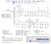
If you can measure the DC resistance of the choke, and the resistance of the power transformer primary winding, and 250V secondary winding, and identify the idle dc load currents on B+ and A+ then the forum can provide further advice using eg. PSUD2.
Yes, or Trobbins suggestionto the marked place in the picture?
- Home
- Amplifiers
- Tubes / Valves
- choke coil application