Can somebody please post me a link to a dead simple class D amp that could be built on a bread board.
I just want to build one to see how they work for educational purposes.
Any leads on this would be fantastic
cheers
I just want to build one to see how they work for educational purposes.
Any leads on this would be fantastic
cheers
i think fully descrete would be the best way to go
I know it's not good for performance but it's
mainly for educational purposes
I know it's not good for performance but it's
mainly for educational purposes
what do you expect?? its like any d-amp...
see (in german, but lokk at the pics 🙂 http://sodfa.so.ohost.de/include.php?path=forum/showthread.php&threadid=146
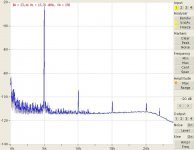
without signal : about 3vss sine at 250khz out, the carrier
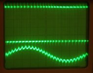
with full signal, a pic:
see (in german, but lokk at the pics 🙂 http://sodfa.so.ohost.de/include.php?path=forum/showthread.php&threadid=146
without signal : about 3vss sine at 250khz out, the carrier
with full signal, a pic:
Attachments
Hi
Do you still have simulation for LTSpice? I don't know how to put LM393 or any other fet in. So with that elements that you had, simulation is running, but Fpwm is ~100kHz.
Do you still have simulation for LTSpice? I don't know how to put LM393 or any other fet in. So with that elements that you had, simulation is running, but Fpwm is ~100kHz.
Hi
Jup now it works, thanks. Do you think if I make the circuit, put +/-47Vdc for supply and use 4 ohm speaker, will it put out 200w+ ??
PS: why is there more current going through upper fet?
Jup now it works, thanks. Do you think if I make the circuit, put +/-47Vdc for supply and use 4 ohm speaker, will it put out 200w+ ??
PS: why is there more current going through upper fet?
Hi
I have see that someone had something called power calculator for LTSpice, do you have it, or where could I find it?
I have see that someone had something called power calculator for LTSpice, do you have it, or where could I find it?
P=U*U/(2*R) , for U=Umax, so 200w /4 ohm = +- 40v supply
dont worry, if currents are not 100% like ideal theory, this is a sim,
in real world , for optimum performance, you have to tune the gate resistors anyway, because depending on the c-gate of your actual mosfets timing will change;
with 100v mosfets, you should not go up to the +- 50v limit, some safety margin is ...good for long life of mosfets...so +- 40v is maximum
for power calc you need to have a secret element in the circuit, i use the lt1076, with is doing nothing useful otherwise,;
start run, then go menu->simulate-> eff.calc. -> mark start
let it run some time, stop or run hole sim.time
then menu->show-> eff.report -> show on shemat.
you see eff calc in circuit
I did not look closely, but are the power supplies on the LM393 fixed at +/- 10 V in the model for that part?alfsch said:ok. here comp2...
Nice job. The simulation works great.
- Status
- Not open for further replies.
- Home
- Amplifiers
- Class D
- Cheap simple class D amp circuit to build.