i have been looking around but i cant find a cheap to build dirty sub... i intend to etch the PCB as i just bought 9 liters of consentrated ferric Chloride...
Cost is a big issue... quality is not...
i intend 150w sub...
thx...
Cost is a big issue... quality is not...
i intend 150w sub...
thx...
ive had a thread on Class d amps... i dun find it usefull as it it so compilcated... the likely hood of it not working is very high due to lousy soldering and insufficient knowledge....
are class b amps that operate at 70% eff. any use to subs?
are class b amps that operate at 70% eff. any use to subs?
national class D amp
I was going to build the national class D amp some time ago, but I was put off by the huge inductors on the output=$$$. Another diy-er said they filter the digital crap out of the signal above the listening range. I was wondering if there was any way to use smaller H inductors for a strictly subwoofer application?
I was going to build the national class D amp some time ago, but I was put off by the huge inductors on the output=$$$. Another diy-er said they filter the digital crap out of the signal above the listening range. I was wondering if there was any way to use smaller H inductors for a strictly subwoofer application?
The app. notes give three options for different HF roll offs, 47uH- 5A, 50uH-5.6A, and 68uH-7.3A.
I must admit, I have had the chips for a while, but never used them because of this inductor problem. If there is a way of DIYing the the inductors then it might come off the back burner!🙂
I must admit, I have had the chips for a while, but never used them because of this inductor problem. If there is a way of DIYing the the inductors then it might come off the back burner!🙂
stole this from the app note
Output Stage Filtering
As common with Class D amplifier design, there are many
trade-offs associated with different circuit values. The output
stage is not an exception. National has found good results
with a 50µF inductor and a 5µF Mylar capacitor (see Figure
1, Typical Audio Application Circuit) used as the output
LC filter. The two-pole filter contains three components; L1
and Cbyp because the LM4651 and LM4652 have a bridged
output. The design formula for a bridge output filter is fC =
1/[2pi(L1 2Cbyp )1/2].
A common mistake is to connect a large capacitor between
ground and each output. This applies only to single-ended applications. In bridge operation, each output sees Cbyp.
This causes the extra factor of 2 in the formula. The alternative
to Cbyp is a capacitor connected between each output,
V0 , and V02 , and ground. This alternative is, however, not
size or cost efficient because each capacitor must be twice
Cbyp’s value to achieve the same filter cutoff frequency. The
additional small value capacitors connected between each
output and ground (C1) help filter the high frequency from the
output to ground . The recommended value for C1 is 0.1µF to
1µF or 2% to 20% of Cbyp.’
Hopefully someone can make sense of the formula, unfortunately I'm just a lowly LAS major, not an engineer.
If there is a way of DIYing the the inductors then it might come off the back burner!
Of all the passive electronic components, inductors are by far the easiest to DIY.
You just need a suitable magnetic core and wire and some patience.
Regards
Charles
P.S.: To be honest, you need to know how to calculate them as well of course but if this is the main problem I can assist.
hi hacknet
Unfortunately it is 68 uH and not 6.8 uH. I think for an active subwoofer where the amp is placed close to the woofer, the filter with the highest cutoff frequency could be used, i.e. the one with a 47 uH coil.
Regards
Charles
Unfortunately it is 68 uH and not 6.8 uH. I think for an active subwoofer where the amp is placed close to the woofer, the filter with the highest cutoff frequency could be used, i.e. the one with a 47 uH coil.
Regards
Charles
Hi hacknet
The inductance would indeed add up if they were connected in series.
Depending on the type of coil this may result in something that lies somewhere between "not very elegant" and "not advisible".
What I'd like to know is the max current those 6.8uH inductors can carry, could it be it's just a few Miliampères (at that price) ?
Regards
Charles
it look a little like a toroidal trafo only smaller... this was from a shop that collect junked pcbs and recovers the parts so that is why it is so cheap...
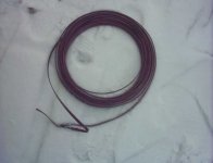
Hi Till
I wouldn't see any problems with this coil if it was used for a >20kW amplifier.
But you will need two of them for a H-bridge.......
I don't like the idea of using coils as large as the subwoofer's driver.
Apart from that you would run into serious EMC problems with air cored coils that large !!!!🙁
A solution i haven't tried yet would be an air-cored toroidal coil but this would require more windings than a cylindrical coil but have less stray-field.
BTW: The maximum current in an inductor isn't determined solely by the wire diameter, the dominant part is played by the core saturation.
A feasible workaround is to use a core with an airgap.
Regards
Charles
Hey two would be no prob, i have more than 20Kg of this material here at the moment.... EMC - yes, i hope nobody aroung knows what i do with this - i try to make a little induction - melting - ofen with these. What about metal enclosure? I build one out of 4mm steel for toroids. Should help.
For the amp i would use some like these i made for the crossovers :
http://www.diyaudio.com/forums/showthread.php?s=&threadid=8218&highlight=spool
posting No. 10
For the amp i would use some like these i made for the crossovers :
http://www.diyaudio.com/forums/showthread.php?s=&threadid=8218&highlight=spool
posting No. 10
I alrerady HAVE used one of those:
http://www.epcos.com/inf/80/db/fer_01/02440248.pdf
Regards
Charles
http://www.epcos.com/inf/80/db/fer_01/02440248.pdf
Regards
Charles
- Status
- Not open for further replies.
- Home
- Amplifiers
- Solid State
- cheap and dirty sub