I built a microphone preamp (common emitter transistors) which runs on lithium batteries. The circuit includes other components such as analog filters and a micro-controller for recording-which is supplied by its own separate battery. It all goes now into an aluminium case to which I need to ground it now.
My question is: Should all signal grounds go to one point on the chassis? Or a couple of grounding points are also recommended? I guess that more than one grounding point would open up for ground loops, but on the other hand I presume it would increase the energy flow into and throughout the chassis, which would make for a better EMI and RFI shield (which in the case of mic preamps is crucial). Please correct me if I'm wrong.
Best regards,
Domingo
It is said that one point ground is better. In my experience this isn't true. In facr one point has no loops but infinite points, also has no loop. In vintage equipment I saw a cable shield welded in several pints to metal chassis. I suggest a try and cut task making your own experience.
Thank you Osvaldo,
Here I found a diagram that made sense to me, since I'm not experienced on this and want to go the safe/standard way. I learned that the path from power supply to chassis should not be shared by other signal grounds (good to know since I was ready to bring all grounds to a screw on the chassis for easiness). Also that anyways input and output connectors/jacks go to chassis, which I suppose will do for the benefits of extra shielding points.
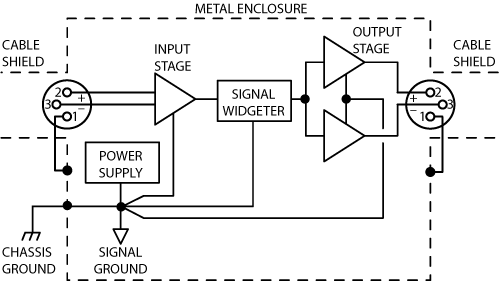
from Grounding and Shielding Audio Devices
Saludos!
Here I found a diagram that made sense to me, since I'm not experienced on this and want to go the safe/standard way. I learned that the path from power supply to chassis should not be shared by other signal grounds (good to know since I was ready to bring all grounds to a screw on the chassis for easiness). Also that anyways input and output connectors/jacks go to chassis, which I suppose will do for the benefits of extra shielding points.
from Grounding and Shielding Audio Devices
Saludos!
BTW,
I have two power sources (one for digital and another for analog sections). Would it be better to interconnect both grounds before shielding to chassis? Or shielding both PSU grounds separately to the chassis is alright as well? If it makes any difference...
I have two power sources (one for digital and another for analog sections). Would it be better to interconnect both grounds before shielding to chassis? Or shielding both PSU grounds separately to the chassis is alright as well? If it makes any difference...
Also that anyways input and output connectors/jacks go to chassis, which I suppose will do for the benefits of extra shielding points.
from Grounding and Shielding Audio Devices
In that drawing, the connectors are not grounded to the chassis. Only Pin 1 of each 3-pin XLR is directly connected to chassis. It looks like the metal housings of the XLR jacks are meant to be isolated from the chassis.
No?
Yes you are right. I took the diagram only as a reference for my unbalanced system, where the housings of the plugs go to chassis– as described in the Rane text and I think as a matter of fact, for the way unbalanced plugs are designed.
- Home
- Source & Line
- Analog Line Level
- Chassis grounding techniques (EMI/RFI) for Mic preamp