You'd have to add a (bypassed) power resistor in the common cathode branch to ground,
to drop the 30VDC. Then ground the grid resistors, instead of them going to -30VDC.
This in effect lowers the B+ voltage by that amount, so there would be lower power output,
all else equal.
to drop the 30VDC. Then ground the grid resistors, instead of them going to -30VDC.
This in effect lowers the B+ voltage by that amount, so there would be lower power output,
all else equal.
Last edited:
Look again. That amp IS cathode bias. Where does the negative come from? A 220 ohm resistor. Bias will vary with current. Current will not vary much.
OK, it is 99% cathode bias. 1% of resistor current comes from the driver. Make no practical difference.
FWIW: that supply voltage and 6.6k load is 19W-23W. (I had a similar amp with 580V and 60W, bit it burned the power transformer, scaled-back to 400V to make a less brutal but much more stage-reliable 20W amp.)
You'd have to add a (bypassed) power resistor in the common cathode branch to ground,
to drop the 30VDC. Then ground the grid resistors, instead of them going to -30VDC.
This in effect lowers the B+ voltage by that amount, so there would be lower power output,
all else equal.
I agree there would be an r/c network added between the each cathode and ground, like the schematic below I just built. Not sure how to calculate those values. Seems from reading here, there are programs like LT spice that can do it. Wondering if a formula exists that could be used? A lot of info here.
Jim
Attachments
Last edited:
FWIW: that supply voltage and 6.6k load is 19W-23W. (I had a similar amp with 580V and 60W, bit it burned the power transformer, scaled-back to 400V to make a less brutal but much more stage-reliable 20W amp.)
I was worried about the 6.6k OPT value too. Initially thought 8k from Z565 would be better, but cathode bias seems to favor higher impedance, like the Heath 51-29, which is 10k.
The "-15V" at the 220 Ohm resistor should be "-30V".
Yes,
good catch.
The "-15V" at the 220 Ohm resistor should be "-30V".
There is a typo, but not sure that is the correct way round?
I think the -15 volts at the 220 ohm resistor is right, and the -30v should also read -15v.
The data sheet gives various g1 volts between -12.5 to -21 volts.
Attachments
Provided this schematic is for a monoblock amp and there isn't a second channel that's fed, you could use a 440 ohm resistor and bypass cap on each 7868 cathode for biasing. If you have trouble finding a 440 ohm 5W resistor, you can put a 6.8K 1W resistor across a 470R/5W resistor and that will get you a 440R 5W resistor.
There is a typo, but not sure that is the correct way round?
I think the -15 volts at the 220 ohm resistor is right, and the -30v should also read -15v.
The data sheet gives various g1 volts between -12.5 to -21 volts.
Hi Alan,
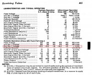
I think you’re right. With – 30 V the 7868’s would be running over their limits.
With Vg1 = -30 V:
Itot = V / R = 30 / 220 = 136 mA
Current through the 7199: 1.3 mA (pentode) + 7.2 mA (triode) = 8.5 mA
Current through the 7868’s: 136 mA – 8.5 mA = 127.5 mA
So 63.7 mA per 7868
Ptot = I x V = 63.7 mA x 390 V = 24.8 Watt
The datasheets give Pamax. = 19 Watt and Pg2max. = 3.3 Watt, so 22.3 Watt total.
With Vg = -15 V:
Itot = 68.2 mA
68.2 – 8.5 = 59.7 mA
So 29.8 mA per 7868
Ptot = 11.6 W
Last edited:
Provided this schematic is for a monoblock amp and there isn't a second channel that's fed, you could use a 440 ohm resistor and bypass cap on each 7868 cathode for biasing.
Yes,
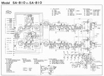
Build 2 channels off shared power supply using PIO SA-810 design for reference only... not keen about voltage doubler for B+.
If you have trouble finding a 440 ohm 5W resistor, you can put a 6.8K 1W resistor across a 470R/5W resistor and that will get you a 440R 5W resistor.
Ok,
What would be your opinion on cap to gnd value? Is it needed?
I think the -15 volts at the 220 ohm resistor is right, and the -30v should also read -15v.
The data sheet gives various g1 volts between -12.5 to -21 volts.
Makes sense per the data sheet.
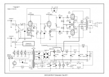
Something else w/ this design seems odd- feedback loop is very aggressive... 270 into 820/10 split on the pentode. For reference, diagram below has very different values. I know overall design dictates individual values, but this seems a bit out of the norm.
Attachments
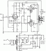
The schematic of TS (including the "-30V" mistake) comes from a RCA Receiving Tube Manual.
I think for GNFB it's the ratio of the two resistors that sets the amount of feedback (provided there's enough gain in the amplifier to start with). So the ratio in the RCA amplifier is 270/10 while the ratio in the Pioneer amp is 4K/100 (or 400/10). So the difference is not that big.
I think for GNFB it's the ratio of the two resistors that sets the amount of feedback (provided there's enough gain in the amplifier to start with). So the ratio in the RCA amplifier is 270/10 while the ratio in the Pioneer amp is 4K/100 (or 400/10). So the difference is not that big.
Last edited:
- Home
- Amplifiers
- Tubes / Valves
- Changing this amp from fixed grid to cathode bias?