From this thread covering my (attempted) repair of an old CS-800,
https://www.diyaudio.com/community/threads/replacement-peavey-cs-800-power-transistors.379993/I found a pair of NOS Motorolas that matched the same part number (as can be seen at the end of my original post). I changed the output board's speaker protection triac (it had shorted the output due to a previous DC offset on the speaker out). I fired the amp up and could hear that the channel was now working for a second... BUT there was 1.5VDC on the speaker at idle (no music playing). Within a few seconds, the triac shorted and the lights dimmed. I now have the same state as I found the amp in (measuring shorts at the output transistors).
So the problem... why could I be seeing 1.5VDC across the speaker at idle? Would this take out the speaker protection triac? I'm guessing even this 1.5VDC being shorted would be enough to kill the output transistor(s) that failed? There was no audio being played when all this happened... Just idling.
You didn‘t determine what else was blown first, or use a dim bulb limiter?
If there was “DC to the speaker” the triac is supposed to come on and blow the fuse. Often this takes transistors with it but it saves the speaker. DC offsets or sticking to a rail are usually caused by problems in the small signal stages (often cheap and easy to fix).
The whole triac circuit should be disconnected, and then the amp fired up on a dim bulb. If there were only a couple of blown output transistors, it could have run that way without them. Once its running that way at low volume, actually making music through speakers, only then do you put in new output transistors.
Yes systems that use an SCR or similar to force a fuse to blow are usually a bad idea, there have been cases of the PCB traces vaporizing in such protection systems - yes it saves the speaker(s), but at very significant cost (and probably a fire-risk too).
Bringing an amp up current-limited is essential in my view for testing - preferrable using resistors between the filter caps and the amp board, since filter caps have a lot of energy to blow things up (even with a dim-bulb tester). I suggest around 470 ohms to each rail initially until you are happy the circuit behaves, then c. 100 ohms so that the rail voltages are more realistic, and some low power testing with load is possible.
Then remove the resistors and perhaps recheck with DBT, before going fully live.
I don't have a dim bulb rig handy and figured everything seemed to check out with a meter. But... expensive lesson on cutting corners. Next time I power it, it will be with current limiting. I don't mind the triac saving expensive speakers while taking out power transistors. The speaker I use for testing however is worth less (to me) than the $4 triac. So in this case, it was a bummer. I actually thought about just omiting the triac. And I have to pull the darn speaker output PCB again. It's not easy access. My one complaint with Hartley Peavey's design on this thing. The rest is very easy to work on.
I'll see if I can find the offset. I don't remember if it was positive or negative but it was there and I should have shut it down immediately instead of scratching my head for a second about what was going on while it blew... lol.
I'll see if I can find the offset. I don't remember if it was positive or negative but it was there and I should have shut it down immediately instead of scratching my head for a second about what was going on while it blew... lol.
I worked on one where the current source load for the VAS went open circuit, sticking me to the negative rail. One MJE350 and two resistors later it was making woofers woof. It can be that simple.
OTOH I repaired a PV-1.3k where the current out the base lines of the blown output transistor took out 108 other parts. All the way back to the DDT transconductance amp, the jfet, and one input op amp. There were some .1 uf 50 v filter caps in the front end open, also some blown caps in the VI limiter circuit. Op amp voltage regulators (zeners) were blown. VI limiter sense resistors were blown, most emitter resistors, stabistor on the heat sink, lots of other resistors & diodes. Very instructive repair, but not a very productive use of time. 100 W light bulb did not allow enough current for the op amp regulator to work on this unit. I limited AC current with the 6 ohm element of a 1200 W room heater.
Yes I learned to leave the triac off while I was doing the debug. It had melted the leads off the PCB anyway instead of blowing the mains breaker. I was putting a Michael Bean nfet disconnect in the rails between filter caps & output board when I parked it. Had trouble making nfets & control fit. I don't need 650 w/ch anyway; my audiences are usually about 12 people. $100 inop CS800s was an easier repair. leaky capacitor & blown fuse in control voltage of switcher supply. Weighs 32 lb less than PV-1.3k, too.
Yes I learned to leave the triac off while I was doing the debug. It had melted the leads off the PCB anyway instead of blowing the mains breaker. I was putting a Michael Bean nfet disconnect in the rails between filter caps & output board when I parked it. Had trouble making nfets & control fit. I don't need 650 w/ch anyway; my audiences are usually about 12 people. $100 inop CS800s was an easier repair. leaky capacitor & blown fuse in control voltage of switcher supply. Weighs 32 lb less than PV-1.3k, too.
Last edited:
I'm going to check the diodes near the zero volt reference for the OT. The nice thing about a stereo amp is that it's easy enough to compare sides. I should have checked more carefully before the first fire up. At least the metal encased TO-3 style transistors fail in a nice enclosed way.
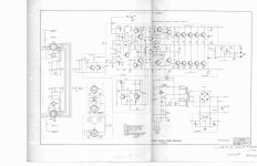
Attachments
And now you have the perfect opportunity to verify your source for the output transistors. If they are dead, crack them open. If the top hat comes off without cutting they are fakes. Having to saw it open is no guarantee of authenticity, but it is necessary. Once open lets see what’s inside.
And now you have the perfect opportunity to verify your source for the output transistors. If they are dead, crack them open. If the top hat comes off without cutting they are fakes. Having to saw it open is no guarantee of authenticity, but it is necessary. Once open lets see what’s inside.
Well it turns out only one output transistor failed and it was one of the original RCA units. I found a bad NE5534N input buffer opamp on that same channel but I don't think that could be it.
Was the transistor failure initiated by DC to the output being shorted out by the triac speaker protector? The RCA house numbered 15024-look-alikes may not be as strong as modern Motorola/On and may not tolerate output shorts as well. The old 2N6259’s would, but I’m not sure PV ever used those because they never mentioned them as substitutes in any of their old service docs. The BGWs did use them.
Was the failed op amp responsible for being stuck to the rail? Or was it the other way around - sometimes being stuck to the rail putting out 81 volts is bad for the op amp because it puts too much current into the feedback input. When I build this type of input stage I use much larger value feedback resistors to keep those input currents down under fault conditions. Blown too many op amps.
Was the failed op amp responsible for being stuck to the rail? Or was it the other way around - sometimes being stuck to the rail putting out 81 volts is bad for the op amp because it puts too much current into the feedback input. When I build this type of input stage I use much larger value feedback resistors to keep those input currents down under fault conditions. Blown too many op amps.
Peavey clamps input to +-15 with diodes, then puts 1000 ohm 1/10 watt resistor before the diodes to blow up if somebody plugs in a 75 W guitar amp speaker output as input. Feedback on a cs800c is a 10 k resistor, up to 43 k in a CS800s.When I build this type of input stage I use much larger value feedback resistors to keep those input currents down under fault conditions. Blown too many op amps.
I was thinking the OT failure was the triac shorting the output. It only took out one thankfully. It produced the normal hiss for a few seconds with the speaker plugged in but I was seeing the couple volts DC on the output. I don't know what took out the opamp, but I'd guess it was dead when I received the amp. I got it for under $50 and now probably have $100 into it. Hoping to have a 2 channel CS-800 before long. Just rigged up a dim bulb between the hot terminals and amp going to power it back up without the shorted OT and triac and see if I can track do the stray couple volts across the speaker terminals.Was the transistor failure initiated by DC to the output being shorted out by the triac speaker protector? The RCA house numbered 15024-look-alikes may not be as strong as modern Motorola/On and may not tolerate output shorts as well. The old 2N6259’s would, but I’m not sure PV ever used those because they never mentioned them as substitutes in any of their old service docs. The BGWs did use them.
Was the failed op amp responsible for being stuck to the rail? Or was it the other way around - sometimes being stuck to the rail putting out 81 volts is bad for the op amp because it puts too much current into the feedback input. When I build this type of input stage I use much larger value feedback resistors to keep those input currents down under fault conditions. Blown too many op amps.
When I started using 47k feedback resistors instead of 10-15k I stopped blowing out input stages during the development process. Except when using OPA2604’s - still wasn’t enough to protect one of those and I wasn’t comfortable with the 220k that it seemed to “need” so I just avoid that family of op amp. That op amp sounds really nice, but if it dies under DC fault conditions or heavy clipping it’s worthless. The 5532 never gave me a bit of greif, but I just prefer the sound of FET op amps in that position as long as the load it’s driving isn’t too terribly heavy requiring a 5532.
The “couple of volts of DC” needs to be fixed - could be anything in the front end including leaky capacitors. Could also be a sign of oscillation - see if the zobel resistor is heating up. That DC offset is enough to trigger the triac and short the amp out. Personally I use relays to open the speaker up instead of short it out. You could build a DC detect and SSR for 20 bucks.
The “couple of volts of DC” needs to be fixed - could be anything in the front end including leaky capacitors. Could also be a sign of oscillation - see if the zobel resistor is heating up. That DC offset is enough to trigger the triac and short the amp out. Personally I use relays to open the speaker up instead of short it out. You could build a DC detect and SSR for 20 bucks.
It turns out that it wasn't really just a couple volts DC across the speaker terminals. I powered it up without Peavey's speaker protection triac in place, and I'm getting almost rail voltage (positive). I had it running dim bulb and powered it down right away when I saw this.
EDIT: Also, I put in the other channel's 5532 op amp and it didn't fail under these conditions. Of course... it's running a lower voltage with the dim bulb in series with the 120VAC hot line.
EDIT: Also, I put in the other channel's 5532 op amp and it didn't fail under these conditions. Of course... it's running a lower voltage with the dim bulb in series with the 120VAC hot line.
It turns out that it wasn't really just a couple volts DC across the speaker terminals. I powered it up without Peavey's speaker protection triac in place, and I'm getting almost rail voltage (positive). I had it running dim bulb and powered it down right away when I saw this.
EDIT: Also, I put in the other channel's 5532 op amp and it didn't fail under these conditions. Of course... it's running a lower voltage with the dim bulb in series with the 120VAC hot line.
Ok... learning more about this problem. I had the guts to leave it on for a second. I get 15 volts at the output upon power up for 3-4 seconds. However, once the amp stabilizes, the speaker output goes to Zero Volts DC. It's about this amount of time that the main caps are charging because the bulb is bright for this period then goes dim. I also notice that once I power down, it also has 15VDC at the output until the caps discharge. I pulled the driver transistors and powered it up and it is the same.
EDIT: I connected up the other (good working) channel and it ALSO has this same phenomenon. So apparently this is normal.
Last edited:
Slow power up on a dim bulb is often ”normal”. This is made worse by the asymmetrical stage following the op amp. They have a pretty big turn on thump when fired up normally too - as the op amp hunts for the proper operating point which sits a couple volts BELOW ground. This can cause you to get stuck to the rail long enough to trigger the triac when you fire up on a dim bulb. Another reason to ditch the triac and use a relay on the speaker. On all my amps I use an LF347 as a quad comparator to do the DC detect for both channels, and feed a 555 timer. That gives me DC shutdown and delayed turn-on to mute the thumps. Mechanical or solid state relays are equally easy to implement (Pick your poison). Plenty of kits available, too.
Slow power up on a dim bulb is often ”normal”. This is made worse by the asymmetrical stage following the op amp. They have a pretty big turn on thump when fired up normally too - as the op amp hunts for the proper operating point which sits a couple volts BELOW ground. This can cause you to get stuck to the rail long enough to trigger the triac when you fire up on a dim bulb. Another reason to ditch the triac and use a relay on the speaker. On all my amps I use an LF347 as a quad comparator to do the DC detect for both channels, and feed a 555 timer. That gives me DC shutdown and delayed turn-on to mute the thumps. Mechanical or solid state relays are equally easy to implement (Pick your poison). Plenty of kits available, too.
I like that idea! I'm just going to leave the triac out for now.
Both channels are now working and it's off the dim bulb and on full power. I don't know for sure but I think what killed the triac the first time was a bad connection on the + rail to the main power amp board. So it was only getting the other 3 connections (GND, neg rail, speaker out) on that 4 pin plug. Anyways, crimped the connector a bit tighter with a pliers and replugged it and verified good connections on all 4 pins and it works well now! I think I'll just leave the triac snipped on the speaker jack board and plan to build something like you have there for the future. Sounds like a perfect setup. I've read using a big ol' relay is a good idea for speaker loads. I'd guess something that will handle 15 amps would be plenty. Really it shouldn't have anything much passing through it when it makes and breaks if the user runs it like it should be run (mixer or preamp on, power amp on, then finally music on).
Now the good side (was good when I bought it) blew the triac and an OT. And it measures positive rail voltage (about 80VDC) at the speaker after I snipped the triac. It was working fine before. Don't know what happened.
And... without a speaker attached to the newly fixed side (also triac snipped) it measures 0V when idling but upon power up or power down it'll show capacitor voltage as it discharges (and momentarily while it charges).
And... without a speaker attached to the newly fixed side (also triac snipped) it measures 0V when idling but upon power up or power down it'll show capacitor voltage as it discharges (and momentarily while it charges).
I bought a PV-1.3k that was so cursed by DC on speaker that a tech had disconnnected rail voltage to channel A, and put a printed label on the back "do not use channel A". Cause was a bad solder joint from the factory on the minus pin of the input op amp. I of course disconnected the triac, which had melted the lands off the PCB anyway. Then I found the cause by connecting a speaker to channel A through a cap, a back to back 10000 uf series a 6800 uf, minus to minus. I then probed around with the DVM. When I touched the bad joint, it would go POP and the DC out would commence or go away. Solder joint looked okay, but wasn't. Takes 2 DVM, one to detect DC, another to probe around looking for stupid voltages.
Your theory about the rail connector may be correct or it may be something else. I'd shake the suspect rail voltage connector wire after setting up a DC detect. It will take trials & data to prove or disprove that theory, plus 100 or 500 other trials, to fix this. Where the DC comes & goes, there is your problem. If a component causes it, heat or cool may be required to cause it to change state. Look for stupid voltages - the PV-1.3k had 138 bad components blown by rail voltage flowing back from base line of bad output transistors blowing parts that weren't rated for 180 vdc. Like 50 v .01 uf bypass caps.
I was trying to stuff in a 4 rail disconnect via nfets when I gave up. The fact that the PV-1.3k had flying speaker ground caused the two speaker grounds to be at different values. That complicated the circuit and I couldn't stuff it all in. I didn't really need 650 w/ch anyway, so the project ended there. Was stuck at the building boards stage when a burglar stole the boards. Not the PV-1.3k, it was too heavy for him.
Last edited:
What a pain this project has been! I'm not the greatest at trouble shooting. But the good thing... I'm getting somewhere. I pulled the two driver transistors and now there is no DC voltage across the speaker terminals.
The transistors measure no shorts on a diode test. I'll have to throw them on my multifunction tester and see how they read. If not those, I guess anything (pre-driver, or something else) before them could be the issue. Obviously somethings turning the rail full on.
EDIT: this is too weird! I put the drivers back in and there's now no DC at the speakers. There WAS near rail voltage on there yesterday. Ahhh... I hate intermittent problems. BUT there is 20VDC or so discharging after the amp is switched off. I suppose a speaker hooked up would quickly drain that. The questions there are... is this normal? And 2, would it destroy the triacs that protect the speakers from DC if they were still intact?
Last edited:
- Home
- Amplifiers
- Solid State
- Changed Peavey CS-800 Output Transistors (with Vintage Motorolas) only to have them blow immediately.