Hi
I've started re-thinking on the amplifier and compression drivers damping factor since I've read an interesting topic regarding on "Concerning blocking caps", I know is an very old topic with several methods/bias/preferences per individuals on how to properly protect expensive compression drivers from power off(or sudden power outages) thumps/pops.
First of, while modern technology audio gear has overcome this drawbacks over time, there is many user with their beloved/old-school amplifier which don't want to replace any time soon, and it is notoriously that many older and/or cheap audio gear may suffer from this power on/off thumps and not necessarily tied to amplifiers but mixing consoles, EQ's etc.
Since researching for quite some time on how to properly protect the CD's but without affecting much the amplifier damping factor, then some years ago I've found a vintage whitepaper buried in this website that I've read, but I purposely ignored a note to what it seems to be an important part, yet not mentioned in today "CD protection cap" threads that I've read around the net recommending the DC blocking cap method.
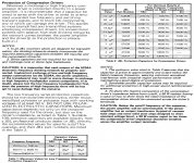
"3. To shunt the reactive component of the compression driver's impedance below horn cutoff, a 50 W resistor having a value of two or three times the rated impedance of the compression driver should be connected across the driver's terminals."
Example:

So if I understand this correctly, this resistor mentioned in the note 3 is a form of a fixed damping?, also apart from lowering the overall driver RE by just tad, is this circuit still being practical and/or effective?
Personally my old-school class A/B amplifiers don't thump when turned off, but when playing music and if a sudden power outage happens, the mains speakers the mid-woofer and the CD makes a chest thumping deafening pop, hence I need the DC blocking capacitor on the CD's unfortunately despite being fully active.
Alternatively if the method denoted on the vintage whitepaper is not really practical today or is not so effective on the driver damping function, I've been thinking on an external relay box to quick disconnect the drivers from the amp and shunt the amp pop in fixed 8Ohms resistors upon either sudden AC power failure or by remote turn on/off chain, then I can have peace of mind with the CD's directly connected to the amp.
I should mention that this is for fully active home hi-fi application and maybe I should not worry much about, but having the driver being fully controlled by the amp's damping is one of the big benefits going active, between I will make some tests/measurements for fun before and after adding a 24-Ohms 20W non-inductive resistor to my 8-Ohms CD's and see if the response don't change much.😉
P.S. I've attached the original "Protection of compression drivers.pdf" vintage whitepaper if someone's interested.
I've started re-thinking on the amplifier and compression drivers damping factor since I've read an interesting topic regarding on "Concerning blocking caps", I know is an very old topic with several methods/bias/preferences per individuals on how to properly protect expensive compression drivers from power off(or sudden power outages) thumps/pops.
First of, while modern technology audio gear has overcome this drawbacks over time, there is many user with their beloved/old-school amplifier which don't want to replace any time soon, and it is notoriously that many older and/or cheap audio gear may suffer from this power on/off thumps and not necessarily tied to amplifiers but mixing consoles, EQ's etc.
Since researching for quite some time on how to properly protect the CD's but without affecting much the amplifier damping factor, then some years ago I've found a vintage whitepaper buried in this website that I've read, but I purposely ignored a note to what it seems to be an important part, yet not mentioned in today "CD protection cap" threads that I've read around the net recommending the DC blocking cap method.
"3. To shunt the reactive component of the compression driver's impedance below horn cutoff, a 50 W resistor having a value of two or three times the rated impedance of the compression driver should be connected across the driver's terminals."
Example:
So if I understand this correctly, this resistor mentioned in the note 3 is a form of a fixed damping?, also apart from lowering the overall driver RE by just tad, is this circuit still being practical and/or effective?
Personally my old-school class A/B amplifiers don't thump when turned off, but when playing music and if a sudden power outage happens, the mains speakers the mid-woofer and the CD makes a chest thumping deafening pop, hence I need the DC blocking capacitor on the CD's unfortunately despite being fully active.
Alternatively if the method denoted on the vintage whitepaper is not really practical today or is not so effective on the driver damping function, I've been thinking on an external relay box to quick disconnect the drivers from the amp and shunt the amp pop in fixed 8Ohms resistors upon either sudden AC power failure or by remote turn on/off chain, then I can have peace of mind with the CD's directly connected to the amp.
I should mention that this is for fully active home hi-fi application and maybe I should not worry much about, but having the driver being fully controlled by the amp's damping is one of the big benefits going active, between I will make some tests/measurements for fun before and after adding a 24-Ohms 20W non-inductive resistor to my 8-Ohms CD's and see if the response don't change much.😉
P.S. I've attached the original "Protection of compression drivers.pdf" vintage whitepaper if someone's interested.
Attachments
The inductive component of the horn driver's impedance rises significantly at resonance, which is normally an octave or so below the crossover crossover frequency. Because the series capacitor is one leg of a potential divider with the driver as the other leg, the rising impedance of the driver at resonance counteracts the rising impedance of the capacitor as frequency goes down, until the driver's impedance starts to fall below resonance.
For example, consider an 8Ω compression driver used above 2kHz with a resonance at 500Hz peaking at 100Ω. The 20µF protection capacitor is chosen to have a series impedance less than half that of the driver at the 2kHz crossover frequency, increasing to 8Ω at 1kHz. However at resonance the rising driver's impedance of 100Ω means the series protection capacitor's reactance of 16Ω at the same frequency is not going to do much at all to limit voltage across the driver's voice coil.
An 22Ω resistor across the voice coil will limit the rise of driver impedance to ~18Ω, forcing about half of the drive voltage to be across the protection capacitor at resonance, or nearly -6dB (¼ power) across the voice coil.
This damping resistor was particularly important in olde days where the compression driver was easily inadvertently connected to the low frequency output of an actively crossed system, or a system with an externally accessible crossover, and the driver thus exposed to significant power outside of its designed frequency band for some time until the user realised something was wrong.
The shunt resistor is unlikely to offer much additional protection against turn on/off transients, so I think you can safely leave it out.
Thanks a lot johnmath for the detailed explanation in regards the driver's impedance behavior and the shunt resistor denoted on the vintage document.
I'm still learning and diving a lot about audio basics and technical stuff and best practices, but got a bit confused by the different recommends across the forums in this regards.😱
Since the shunt resistor is not going to give much of a benefit on amp power transients as you've denoted, and now knowing that it is nothing related to an amplifier's damping factor either, the external relay protection box is more appealing solution if I want the CD's directly connected to the amplifier.
Though since this is for home usage and the CD's never takes much power unlike on PA, I will make an A/B test with a CD directly connected to the amp and the other with the DC blocking cap and see if it makes any audible difference as some claim.
Regards
The series 'protection' capacitor will change the sound for a number of reasons that are the natural consequence of physics. The changes in sound may be subtle and probably will not be obvious in a rapid A/B comparison. If after some time you form an opinion that the sound is different (better or more likely worse) the chances are that you are starting to discern the effect of a series component that is altering the original sound, no matter how subtle those changes are.
Once the signature sound of a degradation is recognised, it is difficult to 'un-hear', at least for some. I always prefer a driver to be connected directly to the amplifier to get the best advantage of a near zero drive source impedance and the consequent mitigation of transducer aberrant behaviour.
Once the signature sound of a degradation is recognised, it is difficult to 'un-hear', at least for some. I always prefer a driver to be connected directly to the amplifier to get the best advantage of a near zero drive source impedance and the consequent mitigation of transducer aberrant behaviour.
There's nothing wrong with a higher damping factor, in this case don't worry about damping.
What can happen is the series impedance affects the response as it interacts with the varying driver impedance.
What you can do is put the driver impedance on a simulator and 'fix it'.
What can happen is the series impedance affects the response as it interacts with the varying driver impedance.
What you can do is put the driver impedance on a simulator and 'fix it'.
@johnmath
Right, pretty sure I will certainly not hear much of a difference while A/B them as I'm not that golden-ear guy in which can tell a diff of passive components and/or cables, but I will definitely give a try with some listening sessions with a variety of music genres.
Between I could also have some fun with REW making some measurements and see whats happening to the response too.
Regards
@AllenB
Hi, I've been having some fun with XSim on this regard too, between the CD in question is the Faital HF10AK/LTH102 combo in which I actively crossing at 1.3KHz LR4.
Past 1KHz the driver presents a impedance bump of about ~18ohms near the 2KHz region but past that region seems pretty linear, however since the blocking capacitor is 33uF and outside(below) the crossover point and I don't push them I should not worry much.
Regards
- Home
- Loudspeakers
- Multi-Way
- CD's + DC blocking cap + damping factor