Looked fo this one and can't find it.
So, looking a the circuit diagrams of a few CD players I've found some, have differing sized filter caps after the rectifier diodes and before the regulators in the +/- supplies.
Can anyone shed any light on this, i.e. why a manufacturer would use two different sizes?
My guess is this is mostly because of rail loading but also to keep costs down.
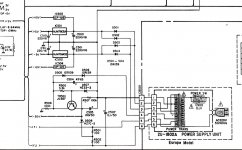
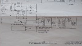
Attached are the PSUs from two cd players that are very similar:
The DCD620 has one 2200µF cap on each rail.
The DCD820 has the same 2200µF cap on the negative rail but a 3300µF on the positive rail. The DCD820 has four additional +5v IC's one for volume control and three for de-glitch (sample and hold)
So, looking a the circuit diagrams of a few CD players I've found some, have differing sized filter caps after the rectifier diodes and before the regulators in the +/- supplies.
Can anyone shed any light on this, i.e. why a manufacturer would use two different sizes?
My guess is this is mostly because of rail loading but also to keep costs down.
Attached are the PSUs from two cd players that are very similar:
The DCD620 has one 2200µF cap on each rail.
The DCD820 has the same 2200µF cap on the negative rail but a 3300µF on the positive rail. The DCD820 has four additional +5v IC's one for volume control and three for de-glitch (sample and hold)
Attachments
Probably due to different consumption/load from + & - rails.
If you look at the old Philips TDA1541 based players, there was far greater consumption/load on the negative rail compared to the positive 🙂
If you look at the old Philips TDA1541 based players, there was far greater consumption/load on the negative rail compared to the positive 🙂