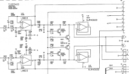
If you look service manuals of popular CD-players based on TDA1541 with OpAmp output you'll se the next thing:
Every buffer is based on NE5532 (NE5534) / LM833 and so on. Everyone has DC blocking capacitor and mute circuit (Some have transistor keys, more expensive - relay mute)
But if you look more detailed you'll se the different output resistor load!
(see the attachments)
In my way (Grundig CD9000) i have 4.7 kOhm (the most populat Philips design)
Sony CDP-s put the 330 kOhm resistor.
Some players like Arcam and others have the 10-47k kOhm!
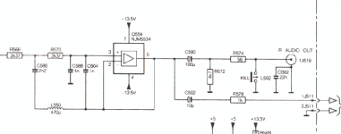
The Philips CD880 have no such "load" resistor!!!
What is it? What it does? Why they are different? And which way is right?
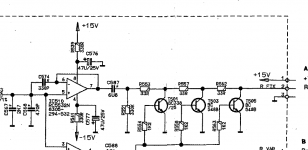
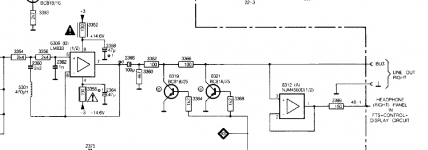
PS: I started this question because i saw interesting thing in my Grundig CD9000 - it has 4.7kOhm load resistor, and the FIX output is paraleled with VAR level poti. and Headphone poti. The pots are 10k and 20k. Asuming them with fixed 4.7k - so the Opamp is loaded by ~2.7k.
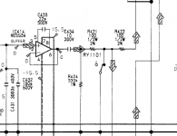
Also, another opamp (6312) is connected to FIX output, but it has no output connection! (see the attachment). The PCB allows to "cut" this connection by removing the solder point and have contacts for 2 resistors between 6312 output and the input of VAR and Headpones pot-s. I cut em and put 150 Ohms. (like in Philips CD670 in attachment)
I heard another sound. It sounds more lightweight, easy to listen!
So the question is "opened" 😀
Every buffer is based on NE5532 (NE5534) / LM833 and so on. Everyone has DC blocking capacitor and mute circuit (Some have transistor keys, more expensive - relay mute)
But if you look more detailed you'll se the different output resistor load!
(see the attachments)
In my way (Grundig CD9000) i have 4.7 kOhm (the most populat Philips design)
Sony CDP-s put the 330 kOhm resistor.
Some players like Arcam and others have the 10-47k kOhm!
The Philips CD880 have no such "load" resistor!!!
What is it? What it does? Why they are different? And which way is right?
PS: I started this question because i saw interesting thing in my Grundig CD9000 - it has 4.7kOhm load resistor, and the FIX output is paraleled with VAR level poti. and Headphone poti. The pots are 10k and 20k. Asuming them with fixed 4.7k - so the Opamp is loaded by ~2.7k.
Also, another opamp (6312) is connected to FIX output, but it has no output connection! (see the attachment). The PCB allows to "cut" this connection by removing the solder point and have contacts for 2 resistors between 6312 output and the input of VAR and Headpones pot-s. I cut em and put 150 Ohms. (like in Philips CD670 in attachment)
I heard another sound. It sounds more lightweight, easy to listen!
So the question is "opened" 😀
Attachments
It's not a critical value, just to prevent thumps when hot plugging. It allows the output capacitor to charge.
IMO, 4.7k is way too low of a load for such opamps, leaving terribly little current left to drive the output line. I'd positively raise that to at least 47k.
As said, the primary purpose of these loads is to prevent static voltage buildup on the output-side of the final coupling cap, i.e., thump prevention.
That 6312 opamp is utterly inexplicable, if the schematic is really correct. It literally does nothing but put a rather unpredictable load on the output line. Good choice to disconnect.
- Status
- Not open for further replies.