Hi All,
Can someone please explain how's the CD players outputs muting function works in the attached drawing?
I have a CD player with an issue, there is no sound output at all but after I removed the 2 transistors Q301/Q302 I get audio perfect output the only issue is that when the CD player is switched off I get white noise from it's outputs.
Thanks
Attachments
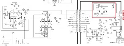
Sounds like the muting itself is OK then.
You need to look at the two inputs 'Mute' and 'P-Mute' and the voltages on the two diodes that drive the mute transistors. Also check the -9v line to those stages.
You need to look at the two inputs 'Mute' and 'P-Mute' and the voltages on the two diodes that drive the mute transistors. Also check the -9v line to those stages.
You might want to try out a relay for muting (beware: it will be too slow when uncorrectable errors occur) at power on/off. This was standard modding in the era of those devices.
All those voltages show the player should be in mute.
The 2.8 volts turns on both of the 'pre biased' transistors. The 8.2V on Q104 collector is fully turning on the two mute transistors.
The 2.8 volts is the reason it is in mute. That voltage needs to be close to zero for it not to mute... so you need to look further forward in the chain and see why that voltage is present.
One question before getting heavy with it... does the player have a remote control and if so is there a Mute button...
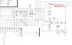
Although 2.8 volts may be a correct level (when muted) it seems a bit unexpected as it seems the chip runs on 5 volts. Normally logic levels would be 0V and 5V but it may be normal for the voltage to fall on that output port when loaded.
Although 2.8 volts may be a correct level (when muted) it seems a bit unexpected as it seems the chip runs on 5 volts. Normally logic levels would be 0V and 5V but it may be normal for the voltage to fall on that output port when loaded.
2.8V, measured from R212
I also tested Q107 and Q108 which are PNP and NPN but they don't measure as "standard" transistor, looking at their data sheet shows that ther is an internal resistor between the base and the emmiter side.
When I tested the Q107 KRA107 transistor (PNP) connecting the multimeter minus to the emmiter side and the plus to the collector I get a reading of 1.154.
Testing the Q108 KRC107 transistor (NPN) connecting the multimeter plus to the emmiter side and the minus to the collector I get a reading of 1.348.
Last edited:
No, no remote or mute button.
BTW it's a Teac PD-H300C CD player.
Thanks.
It is looking like a bit of a strange fault to me. When playing a disc pin 8 should go low (zero volts). Although it would be very unusual for the chip to be faulty, the measured 2.8v as I mentioned earlier seems a bit unexpected. It is neither high nor low for a chip running on 5 volts.
Measured the Q105 which is a KRC107 (NPN) transistor and got the following readings:
B-C - 1.92 on the multimeter
B-E - 1.92
plus on collector, minus on emitter- OL
plus on emitter, minus on collector- 1.83
Is that normal with this type of transistor (epitaxial planar) ?
B-C - 1.92 on the multimeter
B-E - 1.92
plus on collector, minus on emitter- OL
plus on emitter, minus on collector- 1.83
Is that normal with this type of transistor (epitaxial planar) ?
I'm wondering... R212 is there for a reason and if the output port (pin 8) could switch high and low then it would not be needed.
I wonder if the port is just an 'active low' type that can only pull down to ground. The measured 2.8 volts would be because of R212 in series with the internal bias resistors of the transistor... that makes sense.
It still leaves the problem of why pin 8 is not going low. I'm reluctant to blame the chip but perhaps some more sensitive measurements might help.
With Q105 removed can you detect any changes in the voltage on pin 8 for when the player should and should not be muted. Even changes of a few tens of millivolts. If you can then it might point to a failed output on the chip.
You can't test these transistors on a meter... but I don't really believe there is a problem with them. They are operating correctly and doing what the voltage on pin 8 is telling them to do.
- Home
- Source & Line
- Digital Source
- CD player muting circuit