Hi,
For my hybrid amp design, I don't want the VOLUME pot to be at the output of the passive EQ network as in most of traditional designs. Because, the VOL pot becomes a load to the tone stack and this makes the frequency reponse volume-level-dependent. Is that so? (One may say "Then use bigger value VOL pot". I cannot, because I don't have higher than 500k and it's quite hard to find higher values here in Turkey).
I also want the preamp output level to be about max. 0.2Vrms. I'll use the same output as an input to my solid state power amplifier.
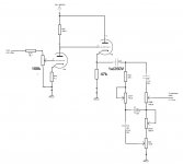
If I'm correct, FMV tone stack can work best if driven /w very low source impedance (e.g. cathode follower). So I thought two different options (as attached pdf files):
Option-1: I've no idea about whether it works well or not. Because, anode voltage of driving stage is about 220VDC and with divider formed by 1M and VOL pot, grid voltage of CF will be about 0.2VDC! (I'm using 1M because this makes preamp output level about 0.2Vrms).
Option-2: I think this makes the driving impedance of tone-stack about 100k. Maybe this cannot bu useful.
NOTE: There's a solid-state buffer after tone-stack and it's purpose is to be preamp output.
Any other ideas? What can I do?
Thanks in advance.
For my hybrid amp design, I don't want the VOLUME pot to be at the output of the passive EQ network as in most of traditional designs. Because, the VOL pot becomes a load to the tone stack and this makes the frequency reponse volume-level-dependent. Is that so? (One may say "Then use bigger value VOL pot". I cannot, because I don't have higher than 500k and it's quite hard to find higher values here in Turkey).
I also want the preamp output level to be about max. 0.2Vrms. I'll use the same output as an input to my solid state power amplifier.
If I'm correct, FMV tone stack can work best if driven /w very low source impedance (e.g. cathode follower). So I thought two different options (as attached pdf files):
Option-1: I've no idea about whether it works well or not. Because, anode voltage of driving stage is about 220VDC and with divider formed by 1M and VOL pot, grid voltage of CF will be about 0.2VDC! (I'm using 1M because this makes preamp output level about 0.2Vrms).
Option-2: I think this makes the driving impedance of tone-stack about 100k. Maybe this cannot bu useful.
NOTE: There's a solid-state buffer after tone-stack and it's purpose is to be preamp output.
Any other ideas? What can I do?
Thanks in advance.
Attachments
Last edited:
Thank you for your reply.
Sorry, forgot to say 🙂 This is a high-gain guitar amp design and the part shown here starts with 5th stage. There are 4 more gain stages before and each of them, as well as the 5th stage, adds harmonic content.
After all the amplification and equalization, I get about 25Vrms. This is quite high for me, so I have to divide it because I need approx 0.2Vrms preamp output. If I place a voltage divider and VOL pot after equalization, this will affect the frequency response.
In either circuit you need a coupling cap between the driving tube and the volume control.
Your second schematic makes the CF unnecessary, as you are now driving the tone stack from a high variable impedance. This will give you exactly the problem you are trying to avoid.
Your second schematic makes the CF unnecessary, as you are now driving the tone stack from a high variable impedance. This will give you exactly the problem you are trying to avoid.
A guitar tone stack does not really need a low impedance source. OK an ordinary source impedance changes the EQ curves compared with a low impedance source, but this will not be obvious to the user. Either way you will have to tweak the component values to get the sound you want. You can also scale all the tone stack impedances up to high values so there is little loading effect on the valve.
Adding a volume pot after the stack does not make the tone dependent on the volume setting, because the resistance of the pot remains the same. I think you may be over-thinking things. You don't *need* a cathode follower in this circuit, at least not from the point of view of EQ control, but you might want a CF because of the distortion tone it produces.
Adding a volume pot after the stack does not make the tone dependent on the volume setting, because the resistance of the pot remains the same. I think you may be over-thinking things. You don't *need* a cathode follower in this circuit, at least not from the point of view of EQ control, but you might want a CF because of the distortion tone it produces.
Then it is in the wrong forum area.rohatkilic said:This is a high-gain guitar amp design
A guitar tone stack does not really need a low impedance source. OK an ordinary source impedance changes the EQ curves compared with a low impedance source, but this will not be obvious to the user. Either way you will have to tweak the component values to get the sound you want. You can also scale all the tone stack impedances up to high values so there is little loading effect on the valve.
Adding a volume pot after the stack does not make the tone dependent on the volume setting, because the resistance of the pot remains the same. I think you may be over-thinking things. You don't *need* a cathode follower in this circuit, at least not from the point of view of EQ control, but you might want a CF because of the distortion tone it produces.
Thank you for your reply, sir.
Most of amp schematics I studied have CF before the tone stack, so I thought that the CF's only (or major) purpose is to drive the tone stack with lower source resistance. But today I learned that a CF can make the sound richer by adding second harmonic distortion 🙂
I'm over-thinking a lot of things 🙂 Because I'm new to valve-based design. Also I built this amp 3 times (with some minor changes) and every turn I encountered a lot of faults (Excessive hum, pops, fuse blowings etc.) 🙂
Anyway, I decided to drive the tone-stack with DC coupled CF and put a 1M resistor+10kB pot in series accross the output of the tone stack (I'll use 10k pot as a volume control).
Thanks again.
😕 Sorry then. I didn't know. 🙁Then it is in the wrong forum area.
Last edited:
- Status
- Not open for further replies.
- Home
- Live Sound
- Instruments and Amps
- Cathode Follower and Volume Pot