Hi folks,
i was wondering what would the best device to use for cascoding the IRF9610/610 on the output stage possibily be.
Also, if you guys have some suggestion on possible better aternative for the 610/9610.
thanks for the attention.
Best.
i was wondering what would the best device to use for cascoding the IRF9610/610 on the output stage possibily be.
Also, if you guys have some suggestion on possible better aternative for the 610/9610.
thanks for the attention.
Best.
I don't know what your circuit parameters are, but the first and most obvious choice would be to use another IRF610/9610.
If you want to use another, similar device, look up the Fairchild equivalents. If you can get away with a somewhat less robust device, I used the Toshiba 2SK2013/2SJ313 MOSFETs in the GR-25 and was pleased with their performance. Watch the ratings, they're not quite the same as normal TO-220 devices. If you want to go bipolar, start with the MJE15030/31 and fan out from there.
Grey
I've used 2SC2238 for the same purposes with good results.
In my circuit bypolar had some advantages respect the "all hexfet" configuration (i.e. another IRF).
Cheers
Marcello
In my circuit bypolar had some advantages respect the "all hexfet" configuration (i.e. another IRF).
Cheers
Marcello
GRollins said:I don't know what your circuit parameters are, but the first and most obvious choice would be to use another IRF610/9610.
If you want to use another, similar device, look up the Fairchild equivalents. If you can get away with a somewhat less robust device, I used the Toshiba 2SK2013/2SJ313 MOSFETs in the GR-25 and was pleased with their performance. Watch the ratings, they're not quite the same as normal TO-220 devices. If you want to go bipolar, start with the MJE15030/31 and fan out from there.
Grey
Hi Grey,
i actually cascoded the 2 devices using another 610/9610 and didn't see any benefit in terms of THD by doing that.
I thought it might be due to the fact that the VDS is forced to be at around 4V which is too low to guarantee a more linear output stage.
I was thinking if there is a good device with higher VGS something like k246 and complementary in to220.
Otherwise i was thinking on use BJTs devices (like Tortello) as toshiba A1358/C3221.
Just quick description of my project: I am building a RIAA phono equalizer.
The first stage will simply drive the 75uS,passive config, time constant.
Than i have arranged another stage with the other 2 time constants in active configuration.
I don't know if it would be optimal to drive an high pass with a pair of J74/K170 biased at 5-6mA.
That's why i am using more robust devices like the IRFs, but, What do you think?
Vgs = 4V?
Um...might I suggest a voltage divider from rail to ground to set the Gate reference voltage to a somewhat higher voltage? 15-20V, minimum. Better still, 30-40V. There's no point in trying to cascode if you're not going to let the parts breathe.
If your gain device (the one on the bottom) has only 4V to work with, you're modulating the everlivin' pee-widdle dookey out of the Drain, thus invoking the Early-riser demons. Higher Vds reduces the percentage.
Grey
If you learn to pit those demons against the transconductance
characteristic, you can get very low distortion.
😎
characteristic, you can get very low distortion.
😎
If you learn to pit those demons against the transconductance characteristic, you can get very low distortion.
how would one go about doing such a thing?
I think there was a simular statement in the ZV3(?) article, where a loveltech j-fet was cascoded. But I could never figure out exactly how you go about doing that. I had to settle for setting the voltage on the gate of the cascode device at a value that allowed the circuit to best reproduce a sine wave -- no flat spots and not overly peaky looking either.
JJ
jupiterjune said:
how would one go about doing such a thing?
I think there was a simular statement in the ZV3(?) article, where a loveltech j-fet was cascoded. But I could never figure out exactly how you go about doing that. I had to settle for setting the voltage on the gate of the cascode device at a value that allowed the circuit to best reproduce a sine wave -- no flat spots and not overly peaky looking either.
Take a close look at the decisions made around the Lovoltech JFET
and read all the text, but go to the ZV9 article (ZV3 will assist you
with a power supply).
JFETs are really good for this, but you can perform the same trick with
a Mosfet.
Unless you like tubes...
😎
Hi Nelson,
thanks for your reply.
I have read the ZV9 article.
I couldn't understand how the bootstrap C5 against the CCS with one leg to ground would improve THD vs the same C5 from out to CCS.
In such a configuration C5 simply looks like a bypass cap for P1 awhile in the other the rule was clear, this is a lack of my knowlege.
I don't know if i have understood wrong, but by modultaing the VDS of the active gain devices and by probing it with a spectrum analyzer it is possible to find a "sweet spot" (for the lowtech device was about 2V) where there is distortion cancellation, correct?
I can't understand how an active JFet device would work better at 2V Vds, how come this low value gives best performance?
For a 2sk170/j74 a Vgs of 8-9V is reccomended for best performance...uhhmm..i am sure it depends upone specific device used.
Last thing: the LUV is a power device and i actually just need a medium power device.
Do you have any suggestion over the classic pair 610/9610?
My output stage is a diamond buffer config and the high capacitance of these two guys here makes things a little more complicated 🙂
Best.
Stefanoo said:I don't know if i have understood wrong, but by modultaing the VDS of the active gain devices and by probing it with a spectrum analyzer it is possible to find a "sweet spot" where there is distortion cancellation, correct?
I can't understand how an active JFet device would work better at 2V Vds, how come this low value gives best performance?
For a 2sk170/j74 a Vgs of 8-9V is reccomended for best performance...uhhmm..i am sure it depends upone specific device used.
Last thing: the LUV is a power device and i actually just need a medium power device.
1) Yes you can find a sweet spot if you go looking for it.
2) In ZV9 with those parts at that current, the sweet spot occurs
around 3V or so.
3) The Lovoltech part is rated at 69 watts, if you dare...
😎
Thanks Mr Pass.
Of course i don't have any audio precision system at my side 🙂 but only a modest EMU with SpectraPlus.
I can still get an idea of distortion, I don't know how reliable it might be.
Mostly i measure it at 1KHz since the card works better at that freq.
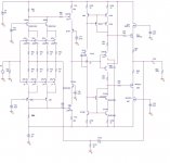
Anyways, the circuit attached is the the MC front i am working on.
With such values i can get 0,00125% THD @1KHz @2V.
Gain is 39dB.
Frequency response: 0.1Hz-820KHz.
DC offset after coupling cap is 0.3mV.
(all the results above has to be intended with matched pars as wihtout them it really differs form that)
Anybody, please feel free to comment on it, if there is any advice on how to improve it,please go ahead.
For the current mirror that biases the output stage i am still playing around and i have changed it a little bit from this schematic as i am still evaulate which one fits the application best.
I have one question: where do you guys think i can control the DC offset?
With the current circuit, before the LP filter i have 3.5V.
Stupidly, but i don't know where an elegant way of zero the output be 🙂
Of course i don't have any audio precision system at my side 🙂 but only a modest EMU with SpectraPlus.
I can still get an idea of distortion, I don't know how reliable it might be.
Mostly i measure it at 1KHz since the card works better at that freq.
Anyways, the circuit attached is the the MC front i am working on.
With such values i can get 0,00125% THD @1KHz @2V.
Gain is 39dB.
Frequency response: 0.1Hz-820KHz.
DC offset after coupling cap is 0.3mV.
(all the results above has to be intended with matched pars as wihtout them it really differs form that)
Anybody, please feel free to comment on it, if there is any advice on how to improve it,please go ahead.
For the current mirror that biases the output stage i am still playing around and i have changed it a little bit from this schematic as i am still evaulate which one fits the application best.
I have one question: where do you guys think i can control the DC offset?
With the current circuit, before the LP filter i have 3.5V.
Stupidly, but i don't know where an elegant way of zero the output be 🙂
Attachments
WOW....All this interest!
It is sad: this forum is fastly dying and people are more interested on "what XLR cable are you using?" than of a technical aspect.
Of course my question on the DC offset is toooo simple for most of you guys....
I know the most obvious answer is: place a trimmer on R74 or R75.
I was looking for something more elegant.
I don't understand if this forum is populated by people who don't know anything about electronics....but i don't think so.....or people who think they are too good to answer to these kind of posts (i think the latter one better!).
There are lots of suggestions, lots improvements that can be done on a circuit.....lots of people...lots of view point......
....instead....nothing.
It seems that we are running out of passion for this hobby/work (for who makes it a work and good for them).
This is called DIYaudio forum and it's supposed to be fun and an helping community.....but most of the time it's been a reason of madness for me and for other people as well......
I posted something and people start criticizing right away.....or insulting me because I said something wrong...or....no interest whatsoever.
Well....I hope this forum can take back and start becoming a self growing community with lots of project nice ideas.
Best Regards.
Stefanoo.
...eeeeasy now.
Maybe people are just busy with other stuff.
Or maybe they are completely overwhelmed by your very nice design (wich by the way looks very much like what I am working on right now).
Here is my suggestion:
The obvious non-trimmer solution would be a servo.
And if you don't want it to disturb your feedback path, you could just make it control the current in your CCS' in Q100 and Q103.
(I have never tried something like that - it was just an idea.)
You could even just replace R164 or 166 with a trimmer, leaving your R74 and R75 to your calculated value, but a servo would also take care of temperature drift.
By the way : Why did you quadrouble you input jfets, instead the VAS or driver jfets? I would say that if any of these needed to be paralleled it would be the driver jfets Q89 and J22. The IRF fets has heavy Ciss and therefore needs heavy current. I recall that they need something like 17mA driver Idle current to be happy. ( most japaneese consumer electronics uses something like 3-5 mA but thats just not enough for high-end sound)
Besides: You should also cascode the drivers, or at least do something to lower their drain voltage. 2SJ74 only does 25volt Drain-gate-voltage, and 2sk170 40v. At maximum voltage swing you have something like 50V peak to peak.
Hi thanks for your post.
I am glad you find the schematic interesting.
1) the inpute jfet are paralleled to achieve lower noise.
The cascode will re-balance the increased input capacitance
--> with regard to this aspect, i don't know if you ever tried this solution: is it better to have just one global cascode for all 4 devices or 4 cascodes (i.e. one for each device)?
2) Why do you suggest it would be better to parallel the drivers? what would the benefit be by doing that?
3) I just don't like the idea of servos. they affect the sound and whenever it is possible to avoid them by just trimming...that would be the way to go for me. As i said DC offset is lower thatn 0.4mV without casing.
I haven't connected the other 25dB of gain stage of the phono stage so 0.4mV might still be an issue at the global output....i will evaluate it.
4) i see what you are saying for cascoding the drivers.
I was planning on doing that.
For maximum swing/optimal performance what voltage would you set DS of the drivers at?
--> do you think the voltages i have set for the cascoding shown on the circuit are ok? or shoud i review something?
5) I know, undortunatelly IRFs have high Capacitance. the bias for the output stage is 20mA although i have notices that at higher bias there is high freq issues on the square wave response, but honestly.....and...stupidly i haven't set the VDS of the drivers at lower values. thus they are working on a not optimal point.
Thank you for your inputs.
Hi,
why the need to cascode the 610/9610 output devices?
Is the dissipation (Pq) just 1% of max Pd?
and yes, j/q22 needs help!!
Why 389 for the mirror CCS? Have you paralleled it for doubled current?
why the need to cascode the 610/9610 output devices?
Is the dissipation (Pq) just 1% of max Pd?
and yes, j/q22 needs help!!
Why 389 for the mirror CCS? Have you paralleled it for doubled current?
Hi Andrew,
I actually didn't see any benefit by cascoding the output in terms of THD but some increase on bandwidth which is not bad.
The main reason i cascoded was itnended to reduce the input capacitance of the pair.
Sorry, where do you see the 389?
Do you mean the input complementary cathode follower at the front end? the 2 quads?
The main reason to parallel them is
1) achieve lower input noise.
If you want to use jfets to load an MC cartridge you have to do something to lower the noise.
As you know the noise of the 2sk/j at loads lower than 10K is not so low.
A way to go, beside using BJT, is to parallel them
2) paralleling offer higher OLG, still since i don't want it to be so high i have to play with the drain resistor a bit.
J21A with 22r in the source.Stefanoo said:Sorry, where do you see the 389?
Ahh.Frequency response: 0.1Hz-820KHz.
you want/require RF amplification from your recordings!
🙂 sorry, it's just a mistake on the schematic.
It is actually a 2sk170 or similar.
Well...i like to achieve wide bandwidth on my circuits. 🙂
It is actually a 2sk170 or similar.
Well...i like to achieve wide bandwidth on my circuits. 🙂
surely there is a sensible limit?Stefanoo said:Well...i like to achieve wide bandwidth on my circuits. 🙂
I like a full decade at either end of the frequency spectrum, i.e. about 2Hz to 200kHz for a power amp and about one octave wider for everything before that, i.e. preamp 1Hz to 400kHz.
Do you need more than that?
Ofcourse - but is it really nescessary? Most amps that uses one pair of K170/J74 in the input still has very good s/n ratio.1) the input jfet are paralleled to achieve lower noise.
[/B]
I have not tried it. Maybe someone else has some experience on this topic....is it better to have just one global cascode for all 4 devices or 4 cascodes (i.e. one for each device)?[/B]
...for increasing the driver-stage Idle without the to92 getting2) Why do you suggest it would be better to parallel the drivers? what would the benefit be by doing that?[/B]

Or you could just cascode...
My point is: This is a more obvious place to parallel than in the input.
So you did actually buildt a real prototype? Nice.3) I just don't like the idea of servos. ...As i said DC offset is lower thatn 0.4mV without casing.[/B]
...I guess you wont be having problems then.
Just make sure your phonostage doesn't have any DC out.
Did you test for temperature and long term drifting? It could change after some hours you know.
Put them at the same ca. 9 volts as the other K170/J74.4) i see what you are saying for cascoding the drivers.
I was planning on doing that.
For maximum swing/optimal performance what voltage would you set DS of the drivers at?
[/B]
I would still parallel at least two pairs for driver though.
5) I know, undortunatelly IRFs have high Capacitance. the bias for the output stage is 20mA ...[/B]
Everybody will say: Go for at least 100mA -150mA.
- Status
- Not open for further replies.
- Home
- Amplifiers
- Pass Labs
- cascode output stage what device?