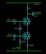
I was just daydreaming the other day and I drew up this cascode cct. I have not built it yet though. It seems to me the advantage of it would be that as the lower gate gets driven positive for example, normally the drain-source voltage decreases as the source voltage rises and the drain voltage drops. Provided we are on the horizontal part of the characteristic curve it may not matter very much. The difference here though is that the lower fet's gate and therefore source voltage rises, so does the upper fet's source and consequently the lower fet's drain. That means the lower fet operates with almost a constant voltage across it no matter what. Seeing it therefore does not traverse the horizontal (voltage) part of it's curve, it's distortion must be somewhat lower. The upper fet has a variable voltage across it of course but this does not matter because it is forced to be a virtually pure current sink.
The drive to the upper fet gate does not contribute to the gain because the lower fet appears to it as a constant current sink. If it therefore cannot change the current it cannot change the signal voltage across the top resistor.
Or have I just re-invented the wheel - again? 🙄
The drive to the upper fet gate does not contribute to the gain because the lower fet appears to it as a constant current sink. If it therefore cannot change the current it cannot change the signal voltage across the top resistor.
Or have I just re-invented the wheel - again? 🙄
Attachments
Circlotron said:I was just daydreaming the other day and I drew up this cascode cct.
Or have I just re-invented the wheel - again? 🙄
I think the circuit you described is known as a bootstrap cascode circuit. Borbely is very fond of using this in his jfet circuits. If the cascode device is a depletion jfet, then you can just tie the gate of the cascode jfet to the source of the bottom FET and you are done, assuming the current range of the devices is properly matched.
Alternatively, you can use a zener to reference the cascode device to the source of the bottom device. I did something like this when I modified the version of the Pass ONO phone stage that I built. I described that here:
http://www.diyaudio.com/forums/showthread.php?postid=326007#post326007
I haven't seen anyone try bootstrapping to the gate of the bottom device, so in that sense it is new. The only drawback is that you are now increasing the load capacitance that must be driven by the previous stage. The advantage of the traditional bootstrap cascode is that the miller capacitance is reduced since you essentially have no variation in gate-drain bias during operation. With the circuit as drawn, you'll now see the varying capacitance of the top device, which defeat the purpose.
Regards,
---Gary
Re: Re: Cascode cct with both mosfet gates driven.
 ThanksGary. 🙂
Hey, that's right! Talk about obvious.GaryB said:With the circuit as drawn, you'll now see the varying capacitance of the top device, which defeat the purpose.
ThanksGary. 🙂- Status
- Not open for further replies.