Hello All! I rescued a beautiful but apparently dead Carver TFM-25 from a pile at a local pawn shop for $30.00. Tried powering it up there and there were no lights and no sound - nothing. But,it was clean as could be on the outside. The clerk said it was a return and must have worked at some point or they would have never taken it in. (Good salesman I thought).
Got it home and cleaned it out and based on my test at the pawn shop I began some testing. I realized I had good power all the way up to the power caps. I had a few problems along the way and removed the power caps and amp caps (six altogether), tested them as good and found an open diode and open cap for the lights/meter circuit.
Cleaned out the amp and put the caps back in and a new cap & diode and powered up. No smoke, no sizzles. I hooked up some cheap speakers and a little FiiO player with the volume all the way down. It worked! No lamps but the meters worked properly. Music from a dead amp. Beautiful. . . . . . .
I played the music for awhile and then paused the player to take a call. During the call I heard a few low-volume pops come from the speakers.
When done with the call I turned up the volume and there was music and the meters worked.
I have a full set of caps to do a full cap replacement but want to nail this down first before I invest the time and effort.
Thoughts?
Besides e-caps over 5 years old, there can also be output transistor heat pads and insulation that can go bad. Sometimes there is a burr on the heatsink that pokes up almost through the pad and causes an amp to be a real dog.
Usually one tests a solid state amp with a 100 W bulb in series with the mains AC source. I built a grounded box with a breaker and an edison socket to keep the mains wires from flying around if they come loose. If the lamp lights, the amp is shorting out. This wasn't big enought to allow the +-15v regulators to function on my 1300 watt amp, so I put a 1200 W room heater in series with the amp instead. If the amp is okay it will play with low volume on the resistance.
I also test with old 100v e-caps minus to minus, in series with the speaker. This affects the bass some but allows me to listen without destroying speakers while I wait for the rare event to happen.
I also use a trash FM radio to exercise the amp instead of a $600 cell phone. (I replaced the dodgy volume pot with a resistor). If you put it on a rock station you can tell music from ultrasonic oscillation on a scope or AC scale of an analog VOM. Music has beats every half second, oscillation does not. If the input cap shorts, I've lost a $1 device.
I fixed an amp that would whang into 180 v dc occasionally. The Dc protector triac kept burning the lands off the PC board. The root cause was a poor solder joint on the socket of the input op amp, the inverting (feedback) pin. Several times "repair persons" had been in the amp replacing output transistors, finally they disconnected the power to the A channel and put a label on it "do not use channel A". I found it by poking around with a meter checking for AC (music).
You can often get schematic diagrams on eserviceinfo.com or other free websites search engines might find you. Not the first page, that is always the pay sites.
The effort to repair one of these is ittermittant dogs not economic, the *****ese serfs work a lot cheaper than you do. If you wish throw it away and buy something shiny & new. Something destined to fail in 7-10 years so you'll have to buy a new one. You can send it to the dump like a real American. I don't follow the plan of the lords of commerce, I run amps 20-55 years old. I learn things that way, too. You can actually buy caps rated 10000 hours service life for some sizes, they are used in industrial motor drives sold to last a dozen years 24/7 in 150 deg F environments. Cost about 30% more than the garbage grade cap used in consumer equipment & prototypes. A tube of 400 deg silicon seal is about $3, you would think manufacturers would use it except the lord of commerce want consumer gear to fail quickly.
See this before buttoning it up. vintage amplifier repair/upgrade manual - diyAudio
Have fun.
Last edited:
Carver ReFurb
Hello,
Thanks. I had forgotten about the link to the vintage amp suggestions. That is very useful. I am with you on the old amps vs. new ones. I like it simple and pure and real.
I too am learning a lot as I go and this will be my fourth amp I have refurbished. This is the first one though that was dead on arrival. Pretty cool and all.
I have some more work to do in nailing down the source of the pop. I have new big power caps in and am awaiting the arrival of the amplifier caps (four of them). Meanwhile, I have all the other small caps I can replace whilst I wait.
Probably worth it. It sounds good to my ear now.
Thanks All!
If the amp is mostly working, sometimes it is better to test with an analog VOM on AC scale, or scope, to find the popping, before replacing things. I make a few bad solder joints, you might too, and two problems is harder to fix than one. As well as once or twice misreading the situation and putting new e-caps in backwards. POP!
Check the power supply rail for big dips. If that is not popping, look for the earliest stage where the popping occurs. After the volume pot, input op amp output or transistor collector, VAS collector, driver stage, output only, which is it? DVM are no use for this, they average over about 4 seconds and miss things. Put a .047 to .47 uf cap in series with the ground probe on AC scale on a VOM to make it not read DC as AC. Or use RF probe if your VOM comes with one.
Then you can poke around the stage where the popping starts to find the problem. Bad solder joints occur, welds can be bad inside transistors diodes or resistors, connectors can be ittermittantly making & breaking, as well as the inevitable e-caps. Actually
having replaced about 400 e-caps in amps plus organs, mostly the old e-caps cause bad sound due to frequency filtering and high resistance, instead of actually breaking down. I've found shorted ceramic caps too, that were taken out by the output stage letting rail voltage rage through the system. Do some of the output transistors have different dates than the other channel? Sign of an incomplete output stage repair, that didn't find everything bad.
Good luck hunting.
Update from Original post
Hi,
I wanted to update about this project. I replaced most of the capacitors, a diode and several transistors in the lamp circuit - including new lamps.
Honestly, I cannot remember them all. I was getting odd voltages that did not make sense. I redid my close inspection of the solder joints and found a micro-break in a trace that was only visible under high magnification. I bridged it with a bit of solder and then insulated the bridge with drop of liquid electrical tape.
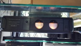
The amp sprung to life and the result is a great sounding happy amp. I set the bias per factory specs and it works great. I love seeing the meters dance.
Thanks for your help here.
James
P.S. I am not sure why the picture is upside down?
Hi,
I wanted to update about this project. I replaced most of the capacitors, a diode and several transistors in the lamp circuit - including new lamps.
Honestly, I cannot remember them all. I was getting odd voltages that did not make sense. I redid my close inspection of the solder joints and found a micro-break in a trace that was only visible under high magnification. I bridged it with a bit of solder and then insulated the bridge with drop of liquid electrical tape.
The amp sprung to life and the result is a great sounding happy amp. I set the bias per factory specs and it works great. I love seeing the meters dance.
Thanks for your help here.
James
P.S. I am not sure why the picture is upside down?
Attachments
Last edited:
Congratulations. Thanks for reporting your success, lots of times there is no end to these threads. Great diagnosis skill finding a micro-break in a PC board land.
Another megaglobal corporation frustrated from a $$$ sale of a new appliance made for $$ by the lowest wage workers they found in the world. Only a few $$ new parts necessary. Easier on the landfill too. Do it Yourself.
Hope this continues working for years to come and provides great music for your future.
- Status
- Not open for further replies.