Hello,
I recently picked up a pair of Carver Amazings. They are in good shape with no ribbon buzzing. They have always been on my bucket list and really do sound amazing IMO. There are a few issues I want to address, one being to build a more robust crossover. I’m using two AB International 600As bridged, one of each one producting around 1k each. At high power levels the crossover gets quite hot and doesn’t smell good, LOL. I’m wanting to keep the xover values the same, but just able to handle more power and dissipate more heat.
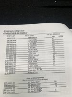
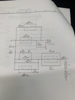
My issue is in the factory service manual the value for L2 in the schematic is 25uH but in the parts list it’s 50uH. The component itself has no markings on it.
Does anyone here have any insight on the correct value?
Any help or insight would be greatly appreciated
I recently picked up a pair of Carver Amazings. They are in good shape with no ribbon buzzing. They have always been on my bucket list and really do sound amazing IMO. There are a few issues I want to address, one being to build a more robust crossover. I’m using two AB International 600As bridged, one of each one producting around 1k each. At high power levels the crossover gets quite hot and doesn’t smell good, LOL. I’m wanting to keep the xover values the same, but just able to handle more power and dissipate more heat.
My issue is in the factory service manual the value for L2 in the schematic is 25uH but in the parts list it’s 50uH. The component itself has no markings on it.
Does anyone here have any insight on the correct value?
Any help or insight would be greatly appreciated
Attachments
Carver made many changes over the runs of its products. Finding the correct schematic can be a bit of a challenge.
Can you measure the impedance of the original coils?
Can you measure the impedance of the original coils?
L2, C3 and R4 form a parallel notch filter with the function of removing a peak in the frequency response of the ribbons.
Best thing to do is buy or borrow an LCR meter in line with BurntFinger's question.
I think he meant to say inductance.
Best thing to do is buy or borrow an LCR meter in line with BurntFinger's question.
I think he meant to say inductance.
Last edited:
I will see if I can measure one this weekend. Bad thing is Im pretty sure they are not the originals and the previous owner used the value in the schematic.
It's possible that the difference in uH values may not be hugely significant in terms of the notch filter action.
It's common to tweak component values in order to adjust notch filter action, so you may be worrying unduly.
It's common to tweak component values in order to adjust notch filter action, so you may be worrying unduly.
Is anyone here able to model the notch filter and find out? I’m just not very knowledgeable on passive crossovers. More of an active type of guy LOL
The resonance frequency is easily calculated. https://en.wikipedia.org/wiki/RLC_circuit
By my quick calculation, 39uH would put the second notch filter's resonance at the third harmonic of the first.
Ed
By my quick calculation, 39uH would put the second notch filter's resonance at the third harmonic of the first.
Ed
Is anyone here able to model the notch filter and find out?
We could work out the respective frequencies and bandwidths of the two possible filter configurations, but we still wouldn't know which one is applicable to the frequency response characteristic of the ribbon tweeter as it is unknown to us.
That makes sense. On a Carver forum most agree that the schematic is probably correct so Im going to go with that and see what happens. Now to try to find a 25uH inductor that will take some power. The biggest one I have found is only 18 gauge or about 300watts🤔We could work out the respective frequencies and bandwidths of the two possible filter configurations, but we still wouldn't know which one is applicable to the frequency response characteristic of the ribbon tweeter as it is unknown to us.
I would have thought the ribbon tweeter would give up the ghost long before its associated crossover components turned to toast!
What precise model of the Carver Amazings do you have? Do you know the power handling of the individual drivers? Have you considered using an active crossover?
What precise model of the Carver Amazings do you have? Do you know the power handling of the individual drivers? Have you considered using an active crossover?
P.S. What makes you think that the inductor in the notch filter is required to handle anywhere near 300 W?
A ribbon tweeter only handles the treble frequencies (naturally!) which will represent only around 10% of the total power supplied to the speaker system.
Plus, the notch filter will only be active over a small fraction of the treble range.
L3 should be just fine as the manufacturers specified it.
Most listening to music is done at single watt amplifier levels and it is highly unusual for a crossover in a domestic speaker to run dangerously hot.
I simply can't imagine that you are pumping circa 1,000 W of power into these Carvers as you seem to suggest in your opening post!
When it comes to dissipating energy as heat, it is the resistors that are the problem.
The resistors associated with the woofer are the ones likely to run hot.
That would be the single resistor R6 in your Carver schematic, and it should be raised up off the crossover board to allow circulation of cooling air and to avoid scorching of the board (which is perhaps what you are smelling).
Correction: In post #12, I meant L2, not L3!
Note that reducing the DCR (Direct Current Resistance) values of the inductors would make the voicing of the speaker different from what the manufacturer intended - something to do with Quality (Q) factor I believe.
Note that L2 already has a small DCR of 0.1 ohm.
Ageing bipolar electrolytic capacitors can be a problem in terms of heat dissipation and any present should be renewed.
I have the original Amazings with two 30” ribbons and four 12” bass drives.What precise model of the Carver Amazings do you have?
I have as I’m usually a big fan of active, but with these I’d just kinda like to keep them “originalish”Have you considered using an active crossover?
I was just saying that an 18 gauge 25uH inductor is only good for 300 watts.P.S. What makes you think that the inductor in the notch filter is required to handle anywhere near 300 W?
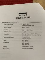
These are not your topic ribbon tweeters. These play almost full range down to 100hz as stated in their factory service manual. See attached pic.A ribbon tweeter only handles the treble frequencies (naturally!) which will represent only around 10% of the total power supplied to the speaker system.
Plus, the notch filter will only be active over a small fraction of the treble range.
I know it seems crazy but these things are just extremely power hungry. Ever Carver suggests used two Carver 1.5t amps bridged which is 1k watts apiece. I was running them on just one amp for around 500 watts a channel, and it was decent but nothing like it is now. Any people are running theirs with well over 1k of power each with no problems except for crossover heating issues.Most listening to music is done at single watt amplifier levels and it is highly unusual for a crossover in a domestic speaker to run dangerously hot.
I simply can't imagine that you are pumping circa 1,000 W of power into these Carvers as you seem to suggest in your opening post!
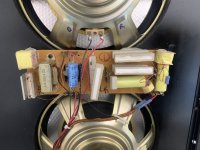
I totally understand what you are saying with the resistors. 50 watt resistors just seem pretty low for as power that is having to be dissipated. That seems to be an easy fix but just getting larger wattage resistors and mounting them to the board with standoffs. As you can see from the attached pic of the crossover, it’s all mounted to just a fiber board so it’s not the smell of an actual fiberglass board.When it comes to dissipating energy as heat, it is the resistors that are the problem.
The resistors associated with the woofer are the ones likely to run hot.
That would be the single resistor R6 in your Carver schematic, and it should be raised up off the crossover board to allow circulation of cooling air and to avoid scorching of the board (which is perhaps what you are smelling).
Yes, I did read that in my quest to learn more about passive crossovers. The one I found is a .07 so not sure if that’s close enough. Any thought on that?Note that reducing the DCR (Direct Current Resistance) values of the inductors would make the voicing of the speaker different from what the manufacturer intended - something to do with Quality (Q) factor I believe.
Note that L2 already has a small DCR of 0.1 ohm.
My plan is to use all Solen caps but with a higher voltage ratings.Ageing bipolar electrolytic capacitors can be a problem in terms of heat dissipation and any present should be renewed.
I do really appreciate your help and advice.
Attachments
Thanks, I now know a lot more about your speakers regarding power handling. 😎
Its a pity that no other Carver Amazings enthusiasts have yet chimed in!
The DCR of L2 does affect the resonant frequency of the notch filter.
The formula for calculating the resonant frequency when the inductor is "impure" can be be found it at the very botom of this link:
https://www.electronics-tutorials.ws/accircuits/parallel-resonance.html
If you're good with units and maths, you could determine whether or not the difference between 0.1 and 0.07 ohm is significant - I'll pass! 😀
Its a pity that no other Carver Amazings enthusiasts have yet chimed in!
The one I found is a .07 so not sure if that’s close enough. Any thought on that?
The DCR of L2 does affect the resonant frequency of the notch filter.
The formula for calculating the resonant frequency when the inductor is "impure" can be be found it at the very botom of this link:
https://www.electronics-tutorials.ws/accircuits/parallel-resonance.html
If you're good with units and maths, you could determine whether or not the difference between 0.1 and 0.07 ohm is significant - I'll pass! 😀
Hey, this have been a big learning experience for me too, so glad we can learn together. That’s what this hobby is all about to me.
Thanks again for your help
I’m pretty good with math so I will have to sit down tonight and see what I come up with.f you're good with units and maths, you could determine whether or not the difference between 0.1 and 0.07 ohm is significant - I'll pass! 😀
Ya, I was hoping a few would chime in. This forum always seems to have the best info compared to most. Hopefully one or two still might🤷It’s a pity that no other Carver Amazings enthusiasts have yet chimed in!
Thanks again for your help

I'm no expert on them, but was involved with a discussion about them previously. I honestly forgot I had modeled the ribbon section. Sorry for the delay.
https://www.diyaudio.com/community/threads/carver-amazing-bi-amping-question.390162/
Filter response with L2 at 25 µH, 0.1 ohm

L2 at 25 µH, 0.07 ohm

L2 at 50 µH

https://www.diyaudio.com/community/threads/carver-amazing-bi-amping-question.390162/
Filter response with L2 at 25 µH, 0.1 ohm
L2 at 25 µH, 0.07 ohm
L2 at 50 µH
Last edited:
I did read that post but there didn’t seem to be an answer to the correct value of L2. At least the difference between .1 and .07 ohms look very minimal so I think I’m going to go with the .25uL .07 ohm and see what happens. Thank you for the graphs BTW.I'm no expert on them, but was involved with a discussion about them previously. I honestly forgot I had modeled the ribbon section. Sorry for the delay.
- Home
- Loudspeakers
- Planars & Exotics
- Carver Amazings crossover help!