Last BAF festivals demonstrate that people are in love with dipoles and open baffles.
I have an idea, to make something in between closed box/ported and open baffle subs, using acoustic resistance vents on the rear side. However, I can't find calculations of acoustic resistance ports for such purpose, only for proper damping. Anyway I will apply active frequency equalisation, so drivers may be use with lower Q than usually used for open baffless, but with long linear excursion.
The question is, how to calculate acoustic resistance vent, for optimal cardioid directivity?
Don't ask, I don't know yet what in such case means "optimum" 🙂
I would say "optimum cardioid characterisics" is
- high rear rejection (say 16 dB or more), but in a small room this might not be too critical.
- having the radiation pattern rather constant within the useable bandwith
- having bandwith as intended (more than 2 octaves with constant directivity might get difficult using a simple resistance box)
- achieve this with cone excursion as small as possible
This would be some goals for design, without discussing how to achieve those and what
the more technical parameters are behind.
Kind Regards
The vent for a "sub" will be somewhere in the 40 Hz or lower range.The question is, how to calculate acoustic resistance vent, for optimal cardioid directivity?
A 40 Hz wave is 28 feet long.
Assuming the distance from the driver to the vent is within 7 feet (1/4 wavelength), it's position makes no difference in directivity whatsoever.
Thank you Oliver;
I will be back after reading and digeting! 🙂
Looks like my idea with acoustic resistance array is not so stupid. ;-)
The vent for a "sub" will be somewhere in the 40 Hz or lower range.
There should be ideally no resonances, just attenuated counter-phase energy radiated. I was thinking about drilling multiple holes on the rear swall of the array.
You could add a rear firing woofer with delay instead. With an acoustic resistance setup, you'll need a lot of displacement to hit the lower registers.
Multiple holes are the equivalent of a single port.There should be ideally no resonances, just attenuated counter-phase energy radiated. I was thinking about drilling multiple holes on the rear swall of the array.
Port output is a phase inversion around Fb of the reverse polarity output from the rear of the speaker.
The output of the port is in phase (but lagging by one cycle) with the front output of the speaker, it does not attenuate the front wave,it reinforces it, regardless of it's position (or number) on the cabinet.
You could add a rear firing woofer with delay instead. With an acoustic resistance setup, you'll need a lot of displacement to hit the lower registers.
There is no difference due to displaced volume needed whether choosing a resistance
box or two drivers separately boxed, if you look at the system from outside.
The volume needed to be displaced at a given frequency for a given SPL depends on the
freefield radiaton pattern chosen and the effective pathlength between the two sources
(front and rear):
Front driver .... rear driver
or
front driver ... rear resistive port
Cardioid patterns can be seen as weighted summation of monopole and dipole.
The dipole component is the one which is costly in terms of displaced volume:
A dipole needs 8 x Vd when lowering the frequency by 1 octave, to keep the SPL constant.
A monopole needs only 4 x Vd when lowering the frequency by 1 octave, to keep the SPL constant.
How (and by which type of element) that needed volume is displaced is completely
irrelevant (additional rear driver or rear port).
In fact one could argue that in case of a resistance box the displaced volume of a given driver
is used double sided, where you need two of that given drivers to have the same volume
displacement in a "two drivers/two closed boxes(chambers)" approach to make a cardioid.
Thus the economic advantage in terms of Vd to be installed is just on the opposite side than you
assume it to be.
Nevertheless there may me reasons to go the "separate boxes with delay" approach but saving
displacement volume in the drivers to be installed does not belong to these reasons.
Kind Regards
Last edited:
Multiple holes are the equivalent of a single port.
...
Nope. There is more resistance (friction) due to motion of the air in the port.
Usually some refined constructions using e.g. felt / foam / textile
resistive slots etc. are used to make up an acoustic resistor which
should act as independent from amplitude as possible (have good
linearity).
The goal in a resistance box is a rather constant group delay between
driver and the rear port. That is not a goal when designing a
BR cabinet.
The alignment of a resistance box is completely different to a high
Qb reflex enclosure.
Nevertheless very similar models could be used to simulate a resistance
box, given that the influence of friction in the port can be modeled and
the effective pathlength is accounted for in the radiation model.
Kind Regards
There will be no big deal I guess to experiment. What else concerns me, distortions in resistance ports, up to turbulent air flow. Let's see...
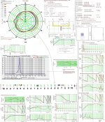
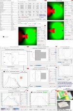
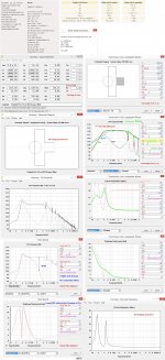
Agree with weltersys. Submitting a few simulations:
b🙂
How did you measure the Rayls values?
Even if you figured out how to build a well-behaved (when measured in half-space) cardioid sub, I don't think that the directivity pattern is going to be able to exist in a normal sized room. The nodes and anti-nodes from all the boundary reflections will swamp it.
In my ramblings with dipole bass, I have come to agree with the idea that below the first room mode (around 50hz in a typical listening room) dipole vs. cardioid vs. monopole has little meaning, and anything besides a monopole is wasting precious excursion. In the 50-100hz octave (and above) dipole bass is a nice thing to hear, I'd imagine cardioid is similar if you are careful to eliminate any box resonances. But at these loooong wavelengths, how do you control the back wave with any sort of enclosure but also have it be non-resonant?
BTW if you place a dipole source with a monopole it "adds up" to a cardioid. If you cross a monopole sub to dipole woofer (and they are acoustically coupled) you will see a cardioid pattern through the crossover region, assuming the room can allow the pattern to exist.
- Home
- Loudspeakers
- Subwoofers
- Cardioid sub with acoustic resistance wvnts - what do you think?