
1.) you'll probably want an output inductor. otherwise the reflected secondary voltage appears across the transformer primary, instead of the supply voltage. the poor switching devices need to charge the output caps AND support this voltage drop! high voltage, high current, high power and high noise!
2.) you will need to look into transformer specs as well. the transformer must be able to support the desired flux excursion. the windings must be able to support the currents.
3.) snubbers may be added to the switching devices to allow the transformer's leakage inductance to discharge into something other then the output capacitance of the FETs.
4.) this push-pull topology has an issue with asymetry. current mode control is used to correct this issue. the applied volt-seconds in each cycle must sum to zero. alternatively, overly resistive windings will allow a resistance to rob volt-seconds from a primary that is about to saturate. this is a subtle effect and the converter can work for many years without issue, until one day...
If you are new to SMPS design, might I reccomend A I Pressman's book, Switching Power Supply Design. This book is a wonderful read, informative, and a decent referance to say the least. it is cited in numerous IEEE articles as well as in documents from magnetics manufacturers.
this "push pull" converter is normally set up as a buck-derived converter. when a switch is engaged, N*Vcc appears on the secondary, and charges the inductor/capacitor. by adjusting duty ratio, and selecting good L C choices, the output voltage will be filtered, giving a DC component of D*N*Vcc, where D is between 0 and 1.
addition of feedback can allow the converter to correct for changes in Vcc, as well as changes in the output current by adjusting D as needed.
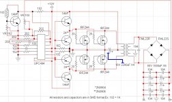
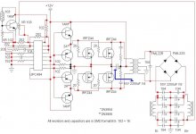
Ok, I implemented the output inductors and the primary side snubbers. Also fixed some schematic typoes, some drive transistors were backwards, and ntc now uses 5V not 12V for power.
I think I may have some problems with the thermal cutout technic I'm using, I don't believe it has any hysteresis so it may turn off and on rapidly due to tolerance changes close to cutout point.
Also, I see how they implement soft start but how do you calculate the values you need to have it work right with your dead time?
Thanks
Dave
Attachments
there will still be a low impednace on the secondary of the transformer at the instant of the switching.
the way the supply works is by applying N*Vp to the secondary when a switch is engaged.
but these output caps appear across the secondary of the transformer. When the switch is engaged, only Vs/N can appear across the switch. if this is less then the supply voltage, then there will be a voltage drop across the switching device. the switching device is capable of high currents, and will draw them.
so now there is a high voltage and a high current on the switching device.
of course this is slightly exagerated, there will be a small leakage inductance that will prevent the current from rising instantly, but i wouldn't rely on that.
For a successful design, familarize yourself with the operation of the "buck regulator". the push-pull design is mostly the same, but with a transformer in between to give a voltage gain. two primaries are used to allow the transformer core to be reset on each cycle.
I'm sorry "theChris" you got me completely lost with that post.
Can you explain it any other way?
Thanks
Dave.
Can you explain it any other way?
Thanks
Dave.
ifrythings said:Can you explain it any other way?
Mind if I try?
The way you added the inductor, you created an extra L/C filter to the output. This may be a good idea, but isn't what Chris was talking about - the inductor should be the first component after the rectifier, before any capacitor. For reasons, see his post again 🙂
Provided that the control circuit has a proper soft-start function implemented, transformer leakage inductance will nicely prevent any current peak during normal operation in unregulated push-pull converters. Actual primary-side current waveforms are rounded and look like the charging voltage waveform in an RC network. The main drawbacks of these converters are just the lack of regulation and the increased ripple current that the output capacitors have to handle.
You can try it without regulation first and implement it later, as it will bring additional problems to solve.
You can try it without regulation first and implement it later, as it will bring additional problems to solve.
OK, I'll try it without regulation then add it latter when I "see" all the problems I'm going to have.
I noticed PC power supply's use the same output desgin, goes: diode -> L -> C -> L - > C then a low(ish) value resistor then to the load. Is that the best way of doing it here too? Or should I go: diode -> L -> c -> load?
Thanks Dave.
P.S Eva, soft start is going to be put in, once I figure out how to. 😕 😀
- Status
- Not open for further replies.
- Home
- Amplifiers
- Power Supplies
- Car SMPS will it work?