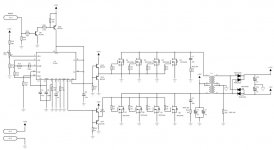
ok, im buildin a car amplifier in my school and i will use quasi´s amplifier desing (will that work in car audio? any other suggestions?) and attached smps schematic.
so, couple questions 🙂
will that remote work with only bc547 & bc557?
what kind of toroid/frequency should i use if i run the amplifier at 2 ohm? and what size of primary/secondary caps?
is the schematic correct? 😀
so, couple questions 🙂
will that remote work with only bc547 & bc557?
what kind of toroid/frequency should i use if i run the amplifier at 2 ohm? and what size of primary/secondary caps?
is the schematic correct? 😀
Osmo said:ok, im buildin a car amplifier in my school and i will use quasi´s amplifier desing (will that work in car audio? any other suggestions?) and attached smps schematic.
so, couple questions 🙂
will that remote work with only bc547 & bc557?
what kind of toroid/frequency should i use if i run the amplifier at 2 ohm? and what size of primary/secondary caps?
is the schematic correct? 😀
The remote-switch will work with just about any combo of NPN-PNPs. Just make sure they have the appropriate Vce ratings.
Typical switching frequency = 2 x BW. So 40kHz is good enough. I don't know about +/-75V rails at 2ohms though. That seems quite dangerous if you don't have a very beefy power supply. +/-25V-40V s I would think would be more realistic, especially since the PS is unregulated.
The caps will depend on how much power you are expecting to get out of it. If you need more power, you will want to add more capacitance. But you will most certainly need more than 1 per rail.
ok. i will probably chance the schematic for 40v rails.http://members.tripod.com/valveaudio/images/schematics/mosfet100.JPG at least that is simple 🙂 Anyone have good schematic for 40v rails?
Osmo said:ok. i will probably chance the schematic for 40v rails.http://members.tripod.com/valveaudio/images/schematics/mosfet100.JPG at least that is simple 🙂 Anyone have good schematic for 40v rails?
You can use the same schematic. The only thing you will have to change is the transformer. It will still need to be a decent size, it just won't need as many windings as the +/-75V one. It doesn't look like there is a part number for the x-former on the schematic anyway. You might want to ask around the forum for specs on a 40kHz transformer for x amount of power.
How much power do you want to get out of the amp?
Based on the level of your questions in your first post I think you are heading for disaster. No offence. A high current SMPS is not something to approach as a beginners project.
By all means build the amp, just run it off a normal house power supply.
By all means build the amp, just run it off a normal house power supply.
How much power do you want to get out of the amp?
100-200w to 4ohm would be enough.
By all means build the amp, just run it off a normal house power supply.
well i just have no need for home amplifier ringt now and i think i can make it work.
richie00boy said:Based on the level of your questions in your first post I think you are heading for disaster. No offence. A high current SMPS is not something to approach as a beginners project.
Gotta start somewhere. I don't think a SMPS is all that difficult a thing to tackle. Why even bother trying to re-invent the wheel anyway? There are tons of examples out there already to use as guides.
I build mine old school style. Rockford Fosgate stuff from the 80's is what I "copy". The switching frequencies are relatively low at 20-30khz, and they are nearly bulletproof when modified to use today's more modern MOSFETS.
Osmo said:ok, im buildin a car amplifier in my school and i will use quasi´s amplifier desing (will that work in car audio? any other suggestions?) and attached smps schematic.
so, couple questions 🙂
will that remote work with only bc547 & bc557?
what kind of toroid/frequency should i use if i run the amplifier at 2 ohm? and what size of primary/secondary caps?
is the schematic correct? 😀
This amp has turned out to be an excellent design for home hi-fi, however I suggest you use this design for your car amp.
http://www.diyaudio.com/forums/showthread.php?postid=594977#post594977
This is because this amp with the rail configurations shown will achieve the best efficiency you can for a class AB design, with almost no voltage drop across the output devices at full power (depends on devices used). I am currently building this module for a subwoofer and I can help you along the way if you wish.
The other amp looses around 6-8 volts across the output devices and if you are only going to use 40v rails this is too much. Not a proble if you use 70+ rails but then you will need lots of output FETS to handle the 2 ohm load.
Cheers
i will probably start doing the pcb for the smps in couple weeks(i will post it here when its finished). Quasi, i will probably do that desing, but if i haven got enough time i have to do something simpler (I have to redo the pcb layout). 🙁
Osmo said:I noticed that there is two positive rails in the scematic, so that is going to be a problem.
Where are the two positive rails?
One for the output stage and another a few volts higher for the driver stage, to ensure max positive swing. This is Quasi's second n-channel amp we are talking about BTW.
richie00boy said:One for the output stage and another a few volts higher for the driver stage, to ensure max positive swing. This is Quasi's second n-channel amp we are talking about BTW.
Ah, I was still looking at the original schematic. That is not too difficult, just connect them with a reverse biased Schottkey diode.
Osmo said:ok, I dont get it, how to hell you get it work with diode?
Nevermind, I was thinking of something else. Of course a diode won't help.
That third rail
The third rail is very easy to set up, just a few extra windings on the transformer secondary, one extra (tiny) bridge rectifier and one capacitor (470uF) will do it. Doesn't even have to be regulated, just reasonably stable. In a switchmode suppply, the regulation used to control the main rails will also keep the third rail stable enough to do the job. Anyway the current drawn is low enough that a cheap regulator would do (zener?).
It's worth it for the extra efficiency gain, but I understand your concerns.
Cheers
I think i will do domething simpler. Anyone have tryed http://members.tripod.com/valveaudio/images/schematics/voltus100.JPG or http://members.tripod.com/valveaudio/images/schematics/mosfet100.JPG
Osmo said:I think i will do domething simpler. Anyone have tryed http://members.tripod.com/valveaudio/images/schematics/voltus100.JPG or http://members.tripod.com/valveaudio/images/schematics/mosfet100.JPG
Your links came up blank.
- Status
- Not open for further replies.
- Home
- General Interest
- Car Audio
- Car amp project