Following discussion in the other thread, performed a few experiments.
This is definitely not a comprehensive research, but a few tests, rather representative though.
Tests are based on my highly lineat symmetric prototype, mentioned here some time ago. Capacitor value - is just the one I had in hand, but enough for 1kHz test. Output signal amplitude is 20v in all tests.
1-st test - 33uF 35v cap serially with 1k resistor as part of global NFB. Positive wire of the cap is connected to the resistor ("signal" side), negative - to the "ground". Output DC offset with no signal comes to -18.5mV, offset at the capacitor -0.66mV (negative offset at the positive cap wire).
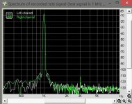
See the spectrum at pic.1 - rather low, but clearly visible 3-rd harmonic.
2-nd test - the cap is "flipped over". DC offset at the output is -17.2mV, at the cap -0.61mV. This time the offset is the "right" one for the cap.
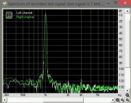
See the spectrum at pic.2 - 3-rd harmonic is roughly 6db lower, than before.
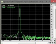
3-rd test - finally, no cap, DC servo is in place. Offset at the output is less than -1mV. Spectrum at pic3 - that's what it's meant to be.
Conclusion - if you don't mind slight THD increase, the cap is a simple working solution. As for me - I prefer minimizing the "bad" 3-rd harmonic. DC servo integrator is my choice.
Another advantage of DC servo - in case DC coupling of the power amp with pre-amplifier, if some offset is coming from pre-amp, DC servo will compensate it (within certain limits, but still), so that the offset at the speakers will be close to zero. Which is always good.
This is definitely not a comprehensive research, but a few tests, rather representative though.
Tests are based on my highly lineat symmetric prototype, mentioned here some time ago. Capacitor value - is just the one I had in hand, but enough for 1kHz test. Output signal amplitude is 20v in all tests.
1-st test - 33uF 35v cap serially with 1k resistor as part of global NFB. Positive wire of the cap is connected to the resistor ("signal" side), negative - to the "ground". Output DC offset with no signal comes to -18.5mV, offset at the capacitor -0.66mV (negative offset at the positive cap wire).
See the spectrum at pic.1 - rather low, but clearly visible 3-rd harmonic.
2-nd test - the cap is "flipped over". DC offset at the output is -17.2mV, at the cap -0.61mV. This time the offset is the "right" one for the cap.
See the spectrum at pic.2 - 3-rd harmonic is roughly 6db lower, than before.
3-rd test - finally, no cap, DC servo is in place. Offset at the output is less than -1mV. Spectrum at pic3 - that's what it's meant to be.
Conclusion - if you don't mind slight THD increase, the cap is a simple working solution. As for me - I prefer minimizing the "bad" 3-rd harmonic. DC servo integrator is my choice.
Another advantage of DC servo - in case DC coupling of the power amp with pre-amplifier, if some offset is coming from pre-amp, DC servo will compensate it (within certain limits, but still), so that the offset at the speakers will be close to zero. Which is always good.
Attachments
Hi, interesting test 🙂
I think you might get more insights into the possible differences, if you tested @ Bass frequences, Say 20Hz - 100Hz !
Also what gk7 said makes sense 😉
I think you might get more insights into the possible differences, if you tested @ Bass frequences, Say 20Hz - 100Hz !
Also what gk7 said makes sense 😉
Thanks.
Half the distortion when the tiny DC bias is of the correct polarity.
20Vac across 1k and 33uF is a mighty high power when the upper leg of the NFB might be seeing 400Vac (gain of 21times).
100Hz and 40Hz @ 5Vac might be more revealing.
Do you have 4 to do a series parallel combination for the same 33uF at these lower frequencies?
Two things will lower the distortions across the cap: Use a bipolar cap and make it reasonable big to lower the crossover frequency. Less AC across the cap results in less distortion. Now given cost and size of a larger bipolar the servo solution becomes attractive. On the other hand a servo takes some time to settle, so you will have a bit of DC at the output at turn on, resulting in a "turn on thump".
- Status
- Not open for further replies.