More details:
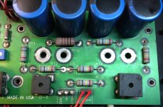
Another strange thing is that on the binding posts that HV winding go to, it says 295-0-375V (see photo) but what I measured directly from the transformer is 300-0-300.
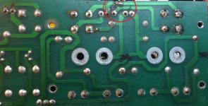
The amp also fail in PSU area before and was repaired by another guy. Looks like he had to modify the circuit by detaching one diode bridge (D-4, notice the cut copper track) from HV winding and add a separate 380VAC transformer with to it.
Actually I prefer to return the amp to original form but this strange PSU circuit really confuses me. I wonder if it really works; and in case it does, will it fail again in the future?
Another strange thing is that on the binding posts that HV winding go to, it says 295-0-375V (see photo) but what I measured directly from the transformer is 300-0-300.
The amp also fail in PSU area before and was repaired by another guy. Looks like he had to modify the circuit by detaching one diode bridge (D-4, notice the cut copper track) from HV winding and add a separate 380VAC transformer with to it.
Actually I prefer to return the amp to original form but this strange PSU circuit really confuses me. I wonder if it really works; and in case it does, will it fail again in the future?
Attachments

Nothing's wrong with the PSU circuit. The designer is just using a center tapped windings as split 2 windings. You can treat it like 2 separate windings on 2 separate bridge rectifiers. 🙂
Nothing's wrong with the PSU circuit. The designer is just using a center tapped windings as split 2 windings. You can treat it like 2 separate windings on 2 separate bridge rectifiers. 🙂
Yes, normally it would be no problem if the 2 windings are separated. But in this case these 2 winding/bridge circuits share 2 same nodes: the centertap and DC ground. This is the 1st time I see PSU circuit like this so I checked several times to make sure there's no mistake when I trace it.
Moreover these B+1 & B+2 supply to different loads: one to power stage (300B PP) and the other to preamp/driver stage (1x12AX7, 2x6SN7) so there surely is imbalance in current demand between them. I also examined the transformer, the 2 halfs of the HV winding are the same in term of voltage and current supply so making them supply different loads seems to be a inefficient design.
The appearance of this circuit in commercial product shows that it can actually work, but I dont know what benefit it makes. In the contrary this amp failed once on the PSU (based on what I see) makes me suspect its durability.
Attached is the amp schematic that I traced, for those who concern.
Thanks,
Duong
Attachments
- Status
- Not open for further replies.